Sunday, September 21, 2014

Explanation Fuse Box Chevrolet Tracker Steering Column 2002 Diagram

Fuse Box Chevrolet Tracker Steering Column 2002 Diagram - This show you about Fuse Box Chevrolet Tracker Steering Column 2002 Diagram.

Fuse Box Chevrolet Tracker Steering Column 2002 Diagram


Fuse
Fuse

Fuse Panel Layout Diagram Parts: heater control unit, blower motor case to heater case duct, heater case, temperature control cable, mode control cable, fresh/recirc control cable, heater core, dampres.
Read More..

Saturday, September 20, 2014

DRM Direct Mixer Using an EF95 6AK5

This hybrid DRM receiver with a single valve and a single transistor features good large-signal stability. The EP95 (US equivalent: 6AK5) acts as a mixer, with the oscillator signal being injected via the screen grid. The crystal oscillator is built around a single transistor. The entire circuit operates from a 6-V supply. The receiver achieves a signal-to-noise ratio of up to 24 dB for DRM signals. That means the valve can hold its own against an NE612 IC mixer. The component values shown in the schematic have been selected for the RTL2 DRM channel at 5990 kHz. That allows an inexpensive 6-MHz crystal to be used. The input circuit is built using a fixed inductor. Two trimmer capacitors allow the antenna matching to be optimized. The operating point is set by the value of the cathode resistor. The grid bias and input impedance can be increased by increasing the value of the cathode resistor. However, good results can also be achieved with the cathode connected directly to ground.

DRM
Read More..

Simple 555 Timer circuit diagram

A lot of guys requested a simple timer schema so this is the schema.This schema runs with main IC NE555. you can change the frequencies of the schema by changing the values of R1, R2,C .This schema runs with 4.5V.


Note :

# Dont supply more than 4.5V
# Build this on a PCB
Read More..

Friday, September 19, 2014

Fuse Box Ford 1997 350 Cube Diagram

Fuse Box Ford 1997 350 Cube Diagram - Here are new post for Fuse Box Ford 1997 350 Cube Diagram.

Fuse Box Ford 1997 350 Cube Diagram


Fuse
Fuse

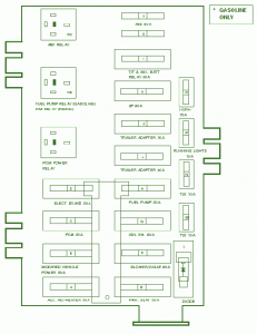
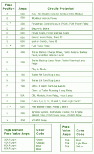
Fuse Panel Layout Diagram Parts: Electronic Brake, power seat, power lumbar seat, blower motor relay, trailer back up lamp relay, trailer running lamp relay, plug in diode, fuel pump relay, trailer bettery charger relay, trailer adapter battery feed, turn/stop lamp, ignition switch, auxilliary , A/C heater, remote keyless entry module, modified vehicle power, powertrain control module, PCM power relay, trailer running lamp, DRL module, horn relay, hood lamp, main lgiht switch, ignition system, insturment cluster, P/A engine, 4WABS relay.
Read More..

Electronic Inverter Wiring diagram Schematic

This is a simple Electronic Inverter Circuit Diagram. Have you ever wanted to run a TV, stereo or other appliance while on the road or camping? Well, this inverter should solve that problem. It takes 12 VDC and steps it up to 120 VAC. The wattage depends on which transistors you use for Q1 and Q2, as well as how "big" a transformer you use for T1. The inverter can be constructed to supply anywhere from 1 to 1000 (1 KW) watts.

Simple Inverter Circuit Diagram


Simple

Parts:
C1, C2 68 uf, 25 V Tantalum Capacitor
R1, R2 10 Ohm, 5 Watt Resistor
R3, R4 180 Ohm, 1 Watt Resistor
D1, D2 HEP 154 Silicon Diode
Q1, Q2 2N3055 NPN Transistor (see "Notes")
T1 24V, Center Tapped Transformer (see "Notes")
MISC Wire, Case, Receptical (For Output)

Notes:
1. Q1 and Q2, as well as T1, determine how much wattage the inverter can supply. With Q1,Q2=2N3055 and T1= 15 A, the inverter can supply about 300 watts. Larger transformers and more powerful transistors can be substituted for T1, Q1 and Q2 for more power.

2. The easiest and least expensive way to get a large T1 is to re-wind an old microwave transformer. These transformers are rated at about 1KW and are perfect. Go to a local TV repair shop and dig through the dumpster until you get the largest microwave you can find. The bigger the microwave the bigger transformer. Remove the transformer, being careful not to touch the large high voltage capacitor that might still be charged. If you want, you can test the transformer, but they are usually still good. Now, remove the old 2000 V secondary, being careful not to damage the primary. Leave the primary in tact. Now, wind on 12 turns of wire, twist a loop (center tap), and wind on 12 more turns. The gauge of the wire will depend on how much current you plan to have the transformer supply. Enamel covered magnet wire works great for this. Now secure the windings with tape. Thats all there is to it. Remember to use high current transistors for Q1 and Q2. The 2N3055s in the parts list can only handle 15 amps each.

3. Remember, when operating at high wattages, this schema draws huge amounts of current. Dont let your battery go dead :-).

4. Since this project produces 120 VAC, you must include a fuse and build the project in a case.

5. You must use tantalum capacitors for C1 and C2. Regular electrolytic will overheat and explode. And yes, 68uF is the correct value. There are no substitutions.

6. This schema can be tricky to get going. Differences in transformers, transistors, parts substitutions or anything else not on this page may cause it to not function.
Read More..

200W Power Amplifier

This 200W power amplifier circuit using IC STK 4050.  STK 4050 is a power amplifier module is very powerful, because the IC is already a module then only needed a little extra components to build a reliable 200W Power Amplifier. Here is a picture series of Power Amplifier ICs 200W use STK 4050 complete with its power supply:

Read More..

Thursday, September 18, 2014

Ford F100 electrical wiring diagram

The wiring diagram comes in color mode, so it should be easier to understand. Please read the Ford F100 electrical wiring diagram comprehensively before doing any wiring work on your For F100 to avoid any wrong wiring connections. Inside the electrical wiring diagram we will see parts like: ignition coil, distributor, ignition switch, instrument cluster lights, courtesy switch, license plate light, high beam indicator, tail light, dome light and switch, light switch, foot dimmer switch, stoplight switch, starter relay, battery, generator, starter, headlight, parking light, temperature switch, and also temperature sender. You will also find the key to abbreviations here.  
Read More..

Fuse Box Ford 2002 F 350 Diesel Power Distribution Diagram

Fuse Box Ford 2002 F-350 Diesel Power Distribution Diagram - Here are new diagram for Fuse Box Ford 2002 F-350 Diesel Power Distribution Diagram.

Fuse Box Ford 2002 F-350 Diesel Power Distribution Diagram


Fuse
Fuse

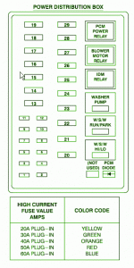
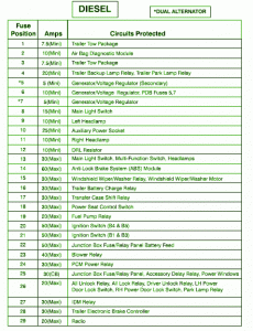
Fuse Panel Layout Diagram Parts: Fuse Panel Layout Diagram Parts: fuel pump relay, ignition switch, junction box fuse, blower relay, PCM power relay, accessory delay relay, transfer case shift relay, power seat control module, auxiliary power socket, Daytime running light resistor, main light switch, multi function switch, anti lock brake system, power window, door lock switch, park lamp relay, IDM relay, trailer electronic brake controller, radio, trailer park lamp, generator/voltage regulator, main light switch, headlamp, trailer tow package, air bag diagnostic module, trailer tow package, trailer back up lamp relay, trailer battery charge relay.
Read More..

12V Battery Charger

This circuit is a high-performance charger for gelled-electrolyte lead-acid batteries. This charger quickly recharges the battery and shuts off at full charge. Initially, charging current is limited to 2 A. As the battery voltage rises, current to the battery decreases, and when the current has decreased to 150 mA,  the charger switches to a lower float voltage, which prevents overcharge.

Circuit diagram :

12V Battery Charger Circuit Diagram

When the start switch is pushed,  the output of the charger goes to 14.5 V. As the battery approaches full charge, the charging current  decreases and the output voltage is reduced from 14.5 V to about 12.5 V, terminating the charging. Transistor Q 1 then lights the LED as a visual indication of full charge.

Read More..

Wednesday, September 17, 2014

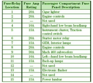
Fuse Box Ford 2002 Mustang DIagram

Fuse Box Ford 2002 Mustang DIagram - Here are new post for Fuse Box Ford 2002 Mustang DIagram.

Fuse Box Ford 2002 Mustang DIagram


Fuse
Fuse

Fuse Panel Layout Diagram Parts: cigar lighter, engine control, headlamp, instrument cluster, traction control switch, starter motor relay, interior lamp, engine control, subwoofer, back up lamp, electronic flasher, power lumbar.
Read More..

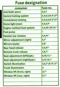
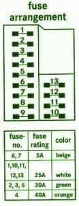
Mercedes Explanation Fuse Box Year C230 Diagram

Fuse Box Mercedes C230 Diagram - Below is Fuse Box Mercedes C230 Diagram.

Fuse Box Mercedes C230 Diagram


Fuse
Fuse

Fuse Panel Layout Diagram Parts: Mirror heater, Rear head release, Fuel pump, Heated rear window, Mirror adjustment, Remote trunk release, Seat adjustment, Switch Illumination, Window lift, Dome light, Engine residual heat system, Anti theft alarm, Central locking system, Convenience locking.
Read More..

Tuesday, September 16, 2014

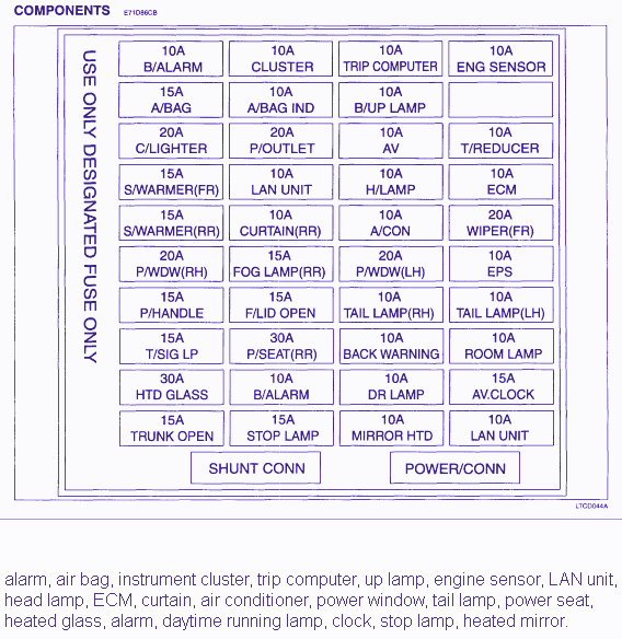
Fuse Box Diagram Of 2004 Kia Amanti

Fuse Box Diagram Of 2004 Kia Amanti
The following circuit shows about Fuse Box Diagram Of 2004 Kia Amanti. The parts fuse panel consist of: heated glass, alarm, daytime running lamp, clock, stop lamp, heated mirror, LAN unit, head lamp, ECM, curtain, air conditioner, power window, tail lamp, power seat, alarm, air bag, instrument cluster, trip computer, up lamp, engine sensor.
Read More..

Fuse Box toyota 1985 celica gt s Convertible Diagram

Fuse Box toyota 1985 celica gt-s Convertible Diagram - Here are new post for Fuse Box toyota 1985 celica gt-s Convertible Diagram.

Fuse Box toyota 1985 celica gt-s Convertible Diagram


Fuse

Fuse Panel Layout Diagram Parts: EFI sysem, battery charger, fan relay, head lamp, hazzard horn, RTR, engine main relay, EFI main relay, headlight control relay, radio.
Read More..

Fuse Box Diagram Of 1990 Chevrolet Cavalier Z24

Fuse Box Diagram Of 1990 Chevrolet Cavalier Z24
The following circuit shows about Fuse Box Diagram Of 1990 Chevrolet Cavalier Z24. The parts fuse panel consist of: computer command control module, tail light, fog light, radio, hazard flasher, fuel pump, oil pressure light, antenna, cruise control, alternator, stop light, instrument light, turn signal, back up light, choke heater, coolant fan, radio, gauges, chime, indicator, defogger, trunk release, ventilation system, crank sensor, power accessories, power window, courtesy light, cigar lighter, wiper.
Read More..

Monday, September 15, 2014

High Voltage regulator schematics

HighIn this series of essentially the same principle with the power supply, but power supply is working to produce high voltage. And high voltage which is regulated by this series becomes more filtered and either used for electronic devices that are not easily damaged.
Read More..

Simple Amplifier Schematic

This Circuit Use a IC BA515 for operation it. This is very simple Amplifier schematic , with only add 8 component , such as resistor and capacitor. Minimum voltage require 3 Volt , this also low voltage amplifier . And maximum voltage require 9 volt. Power output under 10 Watt with impedance 4 Ohm. This circuit is very suitable for small speakers.
See schematic below :


If the circuit above not working may cause as follows :
- Check voltage on the circuit , wether or not the voltage.
- Check wether the components are soldered onto PCB properly.
- Check input and output  wether working or not.
- Check input output cable , if there are disconnected , or a short circuit. Or input connected with ground.
Read More..

10 LED Bar Dot VU Meter Circuit based LM3915

Build a 10 LED Bar Dot VU meter schema based LM3915. It differs in many respects from other applications on the same chip. The schema is intended for those who want a VU meter that is connected directly to the output of an power amplifier.

 10 LED Bar Dot VU Meter Circuit based LM3915 Circuit Diagram


Build

It’s possible to adjust the sensitivity to work with amplifiers that have different output power, you just need to change the value of R1 according to Table 1. In case you did’n find the exact resistor value, then choose the next standard value (for example if you cannot find 33K ohm, then find the 36K ohm), or if you want maximum accuracy you need to put resistors in series or in parallel to achieve the correct value.

Build
 
You can use various types of LEDs (round or square) to get the visual and aesthetic result you want. The switch S1 will allow you to choose whether VU meter will work as a bar or one by one (dot). In position ON [closed switch], the LED operation is Bar, while in position OFF [open switch], the LED operate in Dot. In Bar mode, the power consumption rises because all of the LED will be work and can reach up to 150mA.

For amplifier with two channels is obvious that we should build two identical diagram, one for each channel. The operating voltage of the schema is +12 V. Taking this trend should be done by the tendency of the amp. Usually amps work with voltages which higher than +12 Volts for the schema. For this reason, we must added a component which can decrease, regulate and stabilize the +Vp voltage at +12 Volts. The component we are used is IC2 (LM317) which is an adjustable voltage regulator and stabilizer.

Using a small brushing is necessary because the differences in the potential entry; output is large so that we develop high levels of temperature. The use of R5 helps in voltage drop to descend the voltage at the input of IC2 at lower levels. The calculation of this resistance is more empirically using Ohm’s law. The voltage at the input of IC2 must be higher than +16 Volts. For example, if the voltage of the amplifier is +50 Volts, we should have a voltage drop 50-16 = 34 Volts on the resistance R5. For the electric current, 50mA average is needed by the schema [may be up to 150mA], the value of R5 = V / I = 34/0.05 = 680 ohms 2W. You may need to increase or decrease this value by trials. Because the resistor is going to heat up, then it will be better to put some distance from the PCB.

It will be better to set up and measure the output vltage of the IC2 by adjusting TR1 first, you need yo remove IC1 to secure the IC1. If you are able to supply the stabilized +12 V from somewhere in the amplifier schema, then you’ll need to remove the R5, the IC2 and materials inside the dotted line.

PCB layout design:

PCB

Read More..

Sunday, September 14, 2014

Voltage Tester for Model Batteries Circuit

With a suitable load, the terminal voltage of a NiCd or lithium-ion battery is proportional to the amount of stored energy. This relationship, which is linear over a wide range, can be used to build a simple battery capacity meter. 

Circuit Image :
 Voltage
Voltage Tester for Model Batteries Circuit Image 

This model battery tester has two functions: it provides a load for the battery, and at the same time it measures the terminal voltage. In addition, both functions can be switched on or off via a model remote-control receiver, to avoid draining the battery when it is not necessary to make a measurement. The load network, which consists of a BC517 Darlington transistor (T2) and load resistor R11 (15 Ω /5 W), is readily evident. When the load is active, the base of T1 lies practically at ground level. Consequently, T1 conducts and allows one of the LEDs to be illuminated. 

Circuit Diagram :
Voltage
Voltage Tester for Model Batteries Circuit Diagram

The thoroughly familiar voltmeter schema, which is based on the LM3914 LED driver, determines which LED is lit. The values of R6 and R7 depend on the type and number of cells in the battery. The objective here is not to measure the entire voltage range from 0 V, but rather to display the portion of the range between the fully charged voltage and the fully discharged voltage. Since a total of ten LEDs are used, the display is very precise. For a NiCd battery with four cells, the scale runs from 4.8 V to 5.5 V when R6 = R7 = 2 kΩ. The measurement scale for a lithium-ion battery with two cells ranges from 7.2 V to 8.0 V if R6 = 2 kΩ and R7 = 1 kΩ. 

For remote-control operation, both jumpers should be placed in the upper position (between pin 1 and the middle pin). In this configuration, either a positive or negative signal edge will start the measurement process. A positive edge triggers IC1a, whose output goes High and triggers IC1b. A negative edge has no effect on IC1a, but it triggers IC1b directly. In any case, the load will be activated for the duration of the pulse from monostable IC1b. Use P12 to set the pulse width of IC1a to an adequate value, taking care that it is shorter than the pulse width of IC1b. 

If the voltage tester is fitted into a remote-controlled model, you can replace the jumpers with simple wire bridges. However, if you want to use it for other purposes, such as measuring the amount of charge left in a video camera battery, it is recommended to connect double-throw push-button switches in place of JP1 and JP2. The normally closed contact corresponds to the upper jumper position,while the normally open contact corresponds to the lower position.

Parts :
Resistors:
R1,R2 = 47kΩ
R3 = 100kΩ
R4 = 500kΩ
R5 = 1kΩ
R6,R7 = see text (1% resistors!)
R8 = 1kΩ5
R9 = 1kΩ2
R10 = 330Ω
R11 = 15Ω 5W
R12 = 15kΩ
P1 = 100kΩ preset
Capacitors:
C1 = 10nF
C2 = 100nF
Semiconductors:
D1-D10 = LED, red, high effi-ciency
T1 = BC557
T2 = BC517
IC1 = 74HC123
IC2 = LM3914AN
Miscellaneous:
PC1,PC2,PC3 = solder pin
JP1,JP2 = jumper or pushbutton

PCB Layout :
B.
Voltage Tester for Model Batteries PCB Layout
Streampowers
Read More..

How Work Power Supply Circuit

Power Supply Unit (PSU), the voltage supplies power to a Electronic component. also called ADAPTOR Power supply.
Most electronics component can be plugged into standard electrical outlets in your home. But, there Electronic component not equipped a Power Supply Unit, not include in it, so  cannot be plugged into electrical outlets directly. for exemple; handphone, digital camera, etc.. They are separate from the other part.

How Work Power Supply Circuit?
The Power Supply then converts the AC current to DC current and step down the votage from 220V to 12V, 6V, 5V (depending on the condition of electronic voltage).

In this condition, electric shock safely for touched, unless you hold primary section of the transformator, its dangerous.
Usually factory wrapping the Power Supply in the safe box.

Look the system works below,

How
How Work Power Supply Circuit
Read More..

Soldering iron temperature controller


In most cases I need the stabilize heat for different components like transistor ,IC’s and other semiconductor devices which cannot abide the heat may be it will be damage . Then I make the simple but the important schema for control the heat of soldering iron.
Circuit diagram:


The schema consists of diac, triac, diodes, resister, potentiometer and capacitor.
Parts List:
R1 = 15 Kilo-Ohm
P1 = 250K potentiometer
C1 = 823K, 250V
D1, D2 = 1N4004 or 1N4007
D3 = Diac, bilateral trigger type
Q1 = Triac 500V/25A, BT136
Circuit Operation:


The schema works on RC time constant. The triac is connected in series with soldering iron the reason of choosing the triac is that it work on any polarity so the MT1 (main terminal one) is connected with live wire of 220VAC and MT2 (main terminal two) is connected with soldering iron heater or any of them the diac is connected in series with the gate of triac. It is use for trigger on the gate the R1 and capacitor C1 is the RC time constant and potentiometer is use for changing the trigger or pulses which control the heat of soldering iron manually. The diodes are just for enhancing the ability of charging and discharging and provide protection to diac.

Read More..

Saturday, September 13, 2014

LM3886 68W Power Amplifier

This is a good amplifier schema taken from electronic-diy.com. Built based LM3886, the amplifier capable to deliver up to 68W audio output.

LM3886:


Parts List:

R1 = 10K Ohms
R2 = 10 Ohms 2W see text
R3 = 10 Ohms
R4 = 47K Ohms
R5 = 220K Ohms
R6 = 10K Ohms
R7 = 100K Ohms
L1 0,7uH
IC1 LM3886
C1 = 100NF
C2 = 100NF
C3 = 100NF
C4 = 100UF
C5 = 100UF
C6 = 4,7UF
C7 = 100UF
C8 = 1UF

The amplifier should be supplied by +34 and –34 volts. R2 and L1 is a resistor of 10 ohms / 2 watt coiled with 10 to 12 you exhale of enameled thread AWG 20.

68W Power Amplifier schema diagram based LM3886
Read More..

DTMF Proximity Detector Wiring diagram Schematic

A DTMF-based IR transmitter and receiver pair can be used to realize a proximity detector. The schema presented here enables you to detect any object capable of reflecting the IR beam and moving in front of the IR LED photo-detector pair up to a distance of about 12 cm from it. The schema uses the commonly available telephony ICs such as dial-tone generator 91214B/91215B (IC1) and DTMF decoder CM8870 (IC2) in conjunction with infrared LED (IR LED1), photodiode D1, and other components as shown in the figure. A properly regulated 5V DC power supply is required for operation of the schema.

The transmitter part is configured around dialer IC1. Its row 1 (pin 15) and column 1 (pin 12) get connected together via transistor T2 after a power-on delay (determined by capacitor C1 and resistors R1 and R16 in the base schema of the transistor) to generate DTMF tone (combination of 697 Hz and 1209 Hz) corresponding to keypad digit “1” continuously. LED 2 is used to indicate the tone output from IC3. This tone output is amplified by Darlington transistor pair of T3 and T4 to drive IR LED1 via variable resistor VR1 in series with fixed 10-ohm resistor R14. Thus IR LED1 produces tone-modulated IR light.

DTMFVariable resistor VR1 controls the emission level to vary the transmission range. LED 3 indicates that transmission is taking place. A part of modulated IR light signal transmitted by IR LED1, after reflection from an object, falls on photodetector diode D1. (The photodetector is to be shielded from direct IR light transmission path of IR LED1 by using any opaque partition so that it receives only the reflected IR light.) On detection of the signal by photodetector, it is coupled to DTMF decoder IC2 through emitter-follower transistor T1.

When the valid tone pair is detected by the decoder, its StD pin 15 (shorted to TOE pin 10) goes ‘high’. The detection of the object in proximity of IR transmitter-receiver combination is indicated by LED1. The active-high logic output pulse (terminated at connector CON1, in the figure) can be used to switch on/off any device (such as a siren via a latch and relay driver) or it can be used to clock a counter, etc. This DTMF proximity detector finds applications in burglar alarms, object counter and tachometers, etc.
Sourced by : Streampowers
Read More..

Friday, September 12, 2014

Remote Washing Machine Alert

It is often the case these days that the washing machine and  tumble dryer are installed in an outbuilding  or corner of a garage. This not only makes the kitchen a much quieter place but also leaves room for a dish washer and gives additional cupboard space. The problem now is how to tell when the wash cycle is finished. In bad weather you don’t want to make too many fruitless trips down the garden path just to check if the wash cycle is finished. The author was faced with this problem when he remembered a spare wireless door chime he had. With a few additional components and a phototransistor to passively detect when the washing machine’s ‘end’ LED comes on, the problem was solved. 

Remote Washing Machine Alert Circuit diagram :
Remote
Remote Washing Machine Alert Circuit Diagram

C1 smoothes out any fluctuations in the LED light output (they are often driven by a multiplex signal) producing a more stable DC voltage to inputs 2 and 6 of IC1. The schema is battery powered so the CMOS version of the familiar 555 timer is used for IC1 and IC2. The output of IC1 (pin 3) keeps IC2 reset (pin 4) held Low while there is no light falling on T1. When the wash cycle is finished the LED lights, causing T1 to conduct and the voltage on C1 starts to fall. Changing  the value of R1 will increase sensitivity if the LED is not bright enough. 

When the voltage on C1 falls  below 1/3 of the supply volt-age IC1 switches its output  (pin 3) High, removing the  reset from IC2. T2 conducts  and LED D1 is now lit, sup-plying current to charge C2.  When  the  voltage  across  C2 reaches 2/3 supply IC2  switches its output Low and  C2 is now discharged by pin  7 via R3. The discharge time  is roughly one minute before  the transistor is again switched on. The process repeats as long as light is falling on T1. 

Transistor T2 is a general-purpose small signal NPN type. The open collector output is  wired directly in parallel with the bell push  (which still functions if the transistor is not  switched on). Ensure that transistor output is  wired to the correct bell push terminal (not the side connected to the negative battery  terminal).
Each timer consumes about 60 µA quiescent and the schema can be powered from the transmitter battery. Alternatively a 9 V battery can be substituted; it has much greater capacity than the original mini 12 V battery fitted in the bell push. Before you start construction, check the range of the wireless doorbell to make sure  the signal reaches from the washing machine to wherever the bell will be fitted. 


Author : Götz Ringmann - Copyright : Elektor
Read More..

Build a 12v to 5v DC high efficiency SMPS buck converter using 34063 IC

This project converts 12v DC to a regulated 5v DC at up to 1.8 amps, suitable for driving a tablet computer from a 12v car battery in a power blackout etc.

The schema for this buck converter is nothing original, basically it is the schema from the 34063 IC datasheet, and all I did was to use an external PFET instead of the external PNP transistor shown in the datasheet. The external PFET allows currents up to a few amps at good efficiency, however I have used hard current limiting at 1.8A for safety and good performance in this prototype.

Energy conversion efficiency is very high due mainly to the choice of external components used with the cheap 34063 SMPS IC.

Build


 PCB layout.
The prototype was tested in hardware, please excuse the messiness. The layout is far from ideal, I did it this way to allow easy swapping of parts and just to be lazy, to save the effort of making a PCB. However it still works pretty good, and a proper PCB would improve performance a little bit.

PFET choice.
I did not have a lot of PFETs in my parts box so I used a 100v 8A rated part. This was an SMD PFET so I just tacked it on the bottom of the PCB. It is efficient enough to not need a heatsink even at 5v 1.5A continuous output. The PFET I used was not ideal, its "Rds on" value is about 0.3v at 1.5A (0.2 ohms) which is too high and costs efficiency. Going to a 50v >20A PFET with an RDS <0.1 ohms or <0.05 ohms would give a noticable increase in efficiency.

Schottky diode choice.
I used a TO-220 60v dual 10A schottky diode pack (total 20A). This is a no-brainer, although this is overkill these diodes are only $1-$2 and can also be pulled for free from any old PC PSU and most commercial SMPS supplies. Besides the safety of being very large and over-rated, the main benefit is these diodes have a very low forward voltage drop of <0.3v at 1.5A or 2A and this equates to reduced losses (more efficiency).

Inductor choice.
This is just a commercial "3 amp" 24mm total diameter inductor/choke available from hobby suppliers like Altronics Australia. I think it is a 220uH or 330uH value, but sorry I lost the paperwork.  A few other powdered-iron toroid inductors were tried and it is not that critical. It has 51 turns of 1.0mm diameter wire if that helps. The inductor measured 0.32mV at exactly 1A DC, so DC resitance was measured at 32 milliohms.

Build


Schematic and operation.
Sorry for the hand-drawn schematic! As you can see the schema is minimum parts. It uses just two resitors to drive the PFET from the IC (same as the datasheet), this is not ideal but was done to test the concept and see if a PFET can be driven as easily as the PNP transistor normally is. PFET turnon is good at 0.07uS, but turnoff is not great taking 0.8uS. This costs about 1-2% efficiency. The 560 ohm resistor could be reduced to speed up the turnoff, but this would increase losses in that resistor so it is a tradeoff.

34063 SMPS IC.
The 34063 IC does all the clever stuff, mainly it regulates voltage at 1.25v on VFB pin5. Because of the 6k8:2k2 voltage divider on the output, this gives very close to 5v, I actually saw about 5.01v-4.99v Vout in testing, very nice.

Max current limit resistor.
The resistor between Vin and pin7 sets the max inductor current limiting, this was set by me to roughly 0.18 ohms to give 1.8A current limiting. (Imax = 0.32v / R = 0.32v/0.18 = 1.78A). The current limit is best at slightly above the max required current. This gives better safety and also helps stabilise oscillation.

Caps etc.
CT used the datasheet value of 1nF. That gave oscillator value of 26.2kHz measured on pin3 (with no load), however the whole schema usually operated at 29-33kHz because of the way the regulation works in the IC. The filter caps; 680uF on the input and 1000uF on the output were chosen to be "good enough". Output ripple was approx 25-30mV which is fine.

Measured efficiency!

Vin Iin Pin Vout Iout Pout Eff % 
12.5v 670mA 8.375W 4.99 1.53A 7.63W 91.1%
12.5v 430mA 5.375W 5.00 1.00A 5.00W 93.0%
12.5v 210mA 2.625W 5.00 0.50A 2.50W 95.2%

Note! Readings were taken from meters with only 2 decimal point resolution and were not lab grade accuracy, so there may be a couple of percent error in readings.

Calculating efficiency (at 1.5A output).
The static power losses were seen on the scope and can be calculated;

PFET Rds on period loss = 0.3v / 12.5v = 2.4% loss

DIODE Vf off period loss = 0.28v * 1.53A * 0.56 offduty = 240mW = 2.8% loss

Inductor resistance loss = 1.53A squared * 0.032 ohms = 75mW = 0.9% loss

560 ohm resistor loss = 10.5v squared / 560 * 44% onduty = 87mW = 1.0% loss

Total static losses at 1.53A output = 7.1%
Calculated other (switching) losses = 100% - 91.1% - 7.1% = 1.8%


Scope current L1 inductor (on period) at 5v 1.5 amps.
Above is the on period current through the PFET and L1 inductor. As it is a PFET this is inverted so the pointy bit at the bottom is the max current, the top is zero current. At 1.5A and 32kHz the SMPS is very stable, as switching period is reduced becuase the peaks just hit the 0.32v max current limit set by my choice of 0.18 ohm resistor. (However voltage regulation is still the main regulation).

Duty cycle is about 44%, and current ripple in the inductor is nice and low with inductor current averaging 1.5A (ripple of 0.56A, between 1.22A and 1.78A). The noise spikes I suspect are from from my messy PCB with power and load wires everywhere and scope leads laying around next to the PCB and wiring.


Scope current L1 inductor at 5v 1.0 amps.
Same thing but at 1A. Frequency dropped a bit, closer to the 34063 oscillator freq of 26.2kHz, but still (just) triggering on the max current peaks. Current ripple now larger from approx 0.5A to 1.6A (average output 1A). Timing is still 20uS/hdiv but says 40uS on the Lcd as I had zoomed my h-axis (sorry).


Scope current L1 inductor at 5v 0.5 amps.
Here the L1 current has gone "discontinuous" meaning the L1 current is reduced to zero during the end of the off period, and has to start from 0 amps again during every on period. Typical of the regulation system used in a 34063 IC, the timing will "stutter" as needed to maintain Vout regulation at a steady 5.0v. This does not matter and the 34063 can be quite energy efficiency when "stuttering" in discontinuous mode like this. At less than 0.5 amps the stuttering can become very erratic looking, but this is all normal.


PFET drain/source voltage (main switching waveform).
(The PFET on period is the top of the waveform). Above you can see the PFET turnon (through a 10 ohm resistor) is nice and fast, It was about 0.07uS turnon time. However the turnoff is poor, because the turnoff is from a 560 ohm resistor and is slow at 0.8uS. This costs significant efficiency.

Using an external digital driver (like a 12v CMOS digital buffer/inverter chip?) to drive the PFET would improve turnoff time a lot and increase efficiency, but this was a test of using the simple datasheet example schema with an external PFET (instead of the suggested external PNP) and as proof of concept it still works well enough.


5v DC output showing voltage ripple.
Because it is a switching regulator there will always be some ripple on the DC output voltage. This is shown when running at 5v 1.5A and the ripple is typical and acceptable enough at 30-35mV.

Improving efficiency.
This schema was thrown together very quickly to show how to use a cheap common 34063 IC to get a high efficiency supply from 12v->5v DC at 0-1.5A or so. If you want to invest some effort it can be improved further;

1. My PFET is not a good choice, using a better PFET will give an easy 1% more efficiency, and would be the first choice.

2. The inductor is just an ordinary "off the shelf" type. A properly selected inductor or a good core hand wound for best performance could allow lower operating frequency and less current ripple, and maybe less DC ohms, and maybe pick up another 0.5% efficiency or so. (For lower operating freq CT should also be increased to 1.2nF or 1.5nF etc).

3. The PFET turnoff is too slow. Adding a cheap digital buffer IC could pick up 0.8-1.2% efficiency there from reduced switching losses and reduced loss from the 560 ohm resistor.

4. My PCB has very thin long tracks. Using a well designed PCB with thick short tracks for the main current paths might save 30 milliohms and give maybe 0.5% or more efficiency.

Bill of materials.
* 34063 SMPS 8pin IC (Fairchild/ON Semi/AIS etc, ie MC34063A or NCV34063A).
* 8pin IC socket (optional).
* PFET, rated more than double the input voltage and a few times the desired output current, preferably well under 0.1 ohm Rds on.
* Inductor L1 is a powdered iron toroid of 20-30 mm diameter, with thick wire >1.0mm preferred, 3A rated for a 1.5A capable supply. Value in the 150-470uH range, you may need to try a couple of different types. Ideally current ripple will be <50% at full output current.
* Schottky TO-220 dual 10A or dual 16A diode pack. Choose for low forward voltage, most brands are very good, parts can be found in any old PC PSU.
* 470-1000uF 35v electro cap.
* 1000uF 16-25v electro cap (25v will be larger and generally have a longer life).
* CT 1nF 25-50v ceramic or greencap.
* some 1/4W resistors; 560 ohm, 10 ohm, 6k8, 2k2.
* If you need a test load then a large 10W 4.7 ohm resistor will do.

Modifying the schema for 12v car operation.
This schema was designed for a car battery, generally 13.8v to 12.0v when running. If used in a car the schema needs more protection as the Vin might be >15v at times. I would use a 100 ohm resistor instead of the 10 ohm resistor. Also a 13v zener diode across the 560 ohm resistor will add safety for the PFET. A 12v line filter might also be advised, they can be bought from auto stores.

Modifying the schema for 24v operation.
Use 560 ohms instead of 10 ohms, so it now has two 560 ohm resistors. And again a 13v zener from PFET gate to source pin. With a 24v Vin you should use a higher inductor value and larger inductor core, 470uH and up are recommended.

[b]Modifying the schema for high output currents.[b]
The schema is meant for 5v out, 0-1.8A. It will do ok up to 2.5A just by changing the current limit resistor (at 2.5A the resitor should be 0.12 ohms or so).

Currents up to 5 amps or more should be ok, but use a larger inductor core size rated for more than the max amps you need, and again a larger inductor value helps >470uH is good. The diode pack will be fine, but the PFET should be rated for a few times more current than your max current. If needing 5A output I would use a 40-50v 60A TO-220 PFET which are a common size.

Changing output voltage.
Just change the 6k8 resistor, to change the output voltage to something other than 5.0v. Like most SMPS diagram it works best with roughly 2:1 Vin:Vout ratio, if using different ratios then again increasing the inductor value >470uH will help.


Source: http://forum.allaboutdiagram.com/showthread.php?t=7885 
Read More..

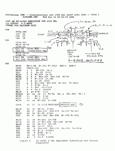
2304 and 3456 MHz Power Amplifiers Wiring diagram Schematic

This is a Simple 2304 and 3456 MHz Power Amplifiers Circuit Diagram

Circuit-Diagram

Read More..

Thursday, September 11, 2014

Speech Filter Wiring diagram Schematic

In communications receivers and microphone amplifiers for transmitting equipment, there is frequently a need for a narrow, low-frequency band-pass filter that lets only the voice band through. This band is usually defined to be the portion of the audio frequency spectrum between approximately 300 Hz and 3300 Hz. In order to implement such a filter, we have calculated the values for two fifth-order Butterworth filters having these corner frequencies and connected them in series. The result is a band-pass filter for the desired pass-band with a skirt steepness of 100 dB/decade.  The first opamp (IC1) acts as a buffer.

Speech Filter Image :
image


The schema can be powered by a unipolar supply voltage between 5 V and 18 V, which is a broad enough range that it should always be possible to find a suitable voltage when building the filter into existing equipment. The current consumption of the filter is only a few milliampères, which should rarely pose a problem. There is fairly wide selection of suitable candidates for the opamps, since the schema is not critical in this regard. In addition to the indicated OP27A, you could consider using a TL081N or even an old-fashioned 741.

Circuit diagram : 
Speech-Filter-Circut-Diagram
Speech Filter Circuit Diagram


Due to unavoidable spreads in component values, the pass-band curve of the filter will never be completely perfect in actual practice. However, the deviations will be very small and in any case inaudible. In the pass-band region, the gain is approximately unity. The printed schema board design shown here allows the speech filter to be built in a very compact form, which can be an important factor if it must be fitted into existing equipment. You can quickly check the fully assembled schema by momentarily measuring the voltages at the inputs and out-puts of the three opamps. Half of the supply voltage should be present at all of these locations.

PCB Layout :
Pcb


Parts LIST:
Resistors:
R1.R2 = 22kΩ
R3,R11,R12,R18,R19 = 100kΩ
R4 = 470Ω
R5 = 150Ω
R6 = 10kΩ
R7 = 18kΩ
R8 = 15kΩ
R9 = 33kΩ
R10 = 82kΩ
R13-R17 = 3kΩ3
Capacitors:
C1,C8,C14,C15 = 100nF
C2 = 1µF MKT
C3-C7,C11 = 22nF
C9 = 33nF
C10 = 18nF
C12 = 10nF
C13 = 4nF7
C16,C17 = 10µF 16V
Semiconductors:
IC1,IC2,IC3 = OP27A, TL081CN
Miscellaneous:
Bt1 = 9-V battery


Source by : Streampowers
Read More..

Emergency Siren Simulator Wiring diagram Schematic

This siren schema simulates police, fire or other emergency sirens that produce an up and down wail.

Simple Emergency Siren Simulator Circuit Diagram

Emergency


The heart of the schema is the two transistor flasher with frequency modulation applied to the base of the first transistor. When the pushbutton is depressed, the frequency of oscillation climbs to a peak and when the button is released, the frequency descends due to the rising and falling voltage on the 22 uF capacitor. The rate of change is determined by the capacitor value and the 100k resistor from the pushbutton.  The oscillation eventually stops if the button is not depressed and the current consumption drops to a tiny level so no power switch is needed.

The 0.1 uF determines the pitch of the siren: A 0.047uF will give a higher pitch siren and a 0.001 uF will give an ultrasonic (at least for me, anyway) siren from 15 to 30 kHz which might have an interesting effect on the neighborhood dogs! The 33k resistor from the collector of the PNP to the base of the NPN widens the pulse to the speaker giving greater volume.

The flasher schema drives a PNP transistor which powers the speaker. This transistor may be a small-signal transistor like the 2N4403 in most applications since it will not dissipate much power thanks to the rapid on-and-off switching. The 100 ohm and 100uF capacitor in series with the speaker limit the current to about 60 mA and they may be replaced with a short schema for a louder siren as long as the transistor can take the increased current. The prototype drew about 120 mA when shorted which is fine for the 2N4403.

Transistor substitutions should be fine - try just about any small-signal transistors but avoid high frequency types so that you do not end up with unwanted RF oscillations.
Read More..

Model Rocket Launcher Wiring diagram Schematic

Model Rocket Launcher Circuit Diagram is a fun and educational hobby. However, it is important to always follow the safety rules for the most enjoyable experience. The schema consists of the launch timer itself and an automatic-off timer. When power is applied to that IC, the countdown LEDs sequence is on until they are all lit. When the last one LED1, is fully lit, transistor Ql saturates, energizing RY2. 

 Model Rocket Launcher Circuit Diagram


 Model

When that happens, a schema between the lantern battery at the launch pad and the nickel-chromium wire is completed; the wire heats up as before, and the rocket is launched. Resistor R4 and capacitor C3 determine the countdown timing; with the values shown it should be approximately 10 seconds. Resistors R3 and R5 set the LED brightness. Safety is of the utmost importance. 

Thats the purpose of the second half of the schema. When RY2 opens, the current flow to Q2 is disrupted. But, because of the presence of R2 and C4, the transistor remains saturated for about 3 seconds. After that, however, the transistor stops conducting and RY1 is de-energized. That cuts off the power to the rest of the schema, and RY2 de-energizes again, breaking the schema to the launch pad. Switch S3 is used to reset the countdown. Once that is done, pressing Si starts the launch sequence; the rest is automatic. Switch S4 is used to latch RY1 manually if needed.
Read More..

Wednesday, September 10, 2014

2W MONO AMPLIFIER

Features


  • CAN DELIVER 2W THD 10% 12V/8Ω
  • INTERNAL FIXED GAIN 32dB
  • NO FEEDBACK CAPACITOR
  • NO BOUCHEROT CELL
  • THERMAL PROTECTION
  • AC SHORT CIRCUIT PROTECTION
  • SVR CAPACITOR FOR BETTER RIPPLE
  • REJECTION
  • LOW TURN-ON/OFF POP
  • STAND-BY MODE

General Description


The device TDA7267 is a new technology Mono Audio Amplifier in MINIDIP package specifically designed for TV application. Thanks to the fully complementary output configuration the device delivers a rail to rail voltage swing without need of boostrap capacitors

Circuit Diagram:
2W MONO AMPLIFIER Circuit Diagram


Read More..

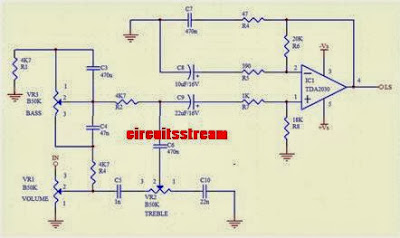
Simple Tone Control Wiring diagram Schematic TDA2030

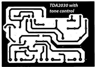
Simple Tone Control Circuit Diagram TDA2030. This is a best tone schema with TDA2030, Tone controls include Bass, Treebel, and Volume. Power amplifier and tone control has been put together in a single PCB. As well as its power supply schema was also used as one with the power amp, and tone control. Making it easier in the installation and will look neat.

 Simple Tone Control Circuit Diagram

 simple tone control circuit diagram

PCB Layout

 
 PCB Design


This amplifier is a mono amplifier type, can be modif for guitar amplifiers. If not coupled amplifier (mic preamp) then you must deactivated potensio treble and bass, why? because if not using a mic preamp and still maintain potensio treble and bass sound input (input) from the guitar will not or the maximum discharge is not tight on the speakers. So you must deactivated a way to decide which directly connected capacitor with the tone control schema, and capacitor were connected directly to potensio volume and input jack.
Read More..