Friday, December 12, 2014

Simple D I Y intercom schematic


This schematic use an old phones as an intercom. You may wish to use a 12 to 24V battery, like a Gel Cell, since the car power or cheap power wall wart style supply is probably too noisy.
Read More..

Battery Charger for 12v

ammeter-battery=charger

This is a design of the circuit diagram of a simple and straight forward battery charger that can be used to charge all type of 12V rechargeable batteries including car batteries.
This circuit is completed with ammeter VU for displaying the current. This is the figure of the circuit.
Read More..

Remote Control IR Jammer

remote-control-circuit

Remote Control IR Jammer

This circuit does all that and more by jamming most IR remote signals. The circuit releases a flood of pulsing IR light that confuses the reciever by corrupting the data stream.
Read More..

Thursday, November 20, 2014

RF Amplifier circuit with 2SC1970 2N4427

RF power amplifier circuit of this work is based on the transistor 2SC1970 and 2N4427. The set output power of 88-108 MHz FM RF Amplifier With 2SC1970 is about 1.3W and the input driver is 30-50mW. RF driver amplifier circuit uses a 2N4427 and its power amplifier using a transistor 2SC1970.

At the time of the amplifier circuit tuning FM 88-108 MHz RF Amplifier With 2SC1970 should use the power meter / watt meter or SWR or RF field can also use the meter. RF amplifier circuit can work from the frequency of 88-108 MHz.

RF Amplifier

Circuit of 88-108 MHz FM RF Amplifier With RF 2SC1970 can radiate far enough. At the time of tuning you should use a 50 Ohm dummy load. For the input signal should be installed to regulate the VR level so as not to over-modulation (30-50mW).
Read More..

Audio Amplifier Circuits 10W with Bass boost

Parts:
P1 22K Log.Potentiometer (Dual-gang for stereo)
P2 100K Log.Potentiometer (Dual-gang for stereo)
R1 820R 1/4W Resistor
R2,R4,R8 4K7 1/4W Resistors
R3 500R 1/2W Trimmer Cermet
R5 82K 1/4W Resistor
R6,R7 47K 1/4W Resistors
R9 10R 1/2W Resistor
R10 R22 4W Resistor (wirewound)
C1,C8 470nF 63V Polyester Capacitor
C2,C5 100uF 25V Electrolytic Capacitors
C3,C4 470uF 25V Electrolytic Capacitors
C6 47pF 63V Ceramic or Polystyrene Capacitor
C7 10nF 63V Polyester Capacitor
C9 100nF 63V Polyester Capacitor
D1 1N4148 75V 150mA Diode
IC1 NE5532 Low noise Dual Op-amp

Q1 BC547B 45V 100mA NPN Transistor
Q2 BC557B 45V 100mA PNP Transistor
Q3 TIP42A 60V 6A PNP Transistor
Q4 TIP41A 60V 6A NPN Transistor
J1 RCA audio input socket
Power supply parts:
R11 1K5 1/4W Resistor
C10,C11 4700uF 25V Electrolytic Capacitors
D2 100V 4A Diode bridge
D3 5mm. Red LED
T1 220V Primary, 12 + 12V Secondary 24-30VA Mains transformer
PL1 Male Mains plug
SW1 SPST Mains switch

Comments:
This design is based on the 18 Watt Audio Amplifier, and was developed mainly to satisfy the requests of correspondents unable to locate the TLE2141C chip. It uses the widespread NE5532 Dual IC but, obviously, its power output will be comprised in the 9.5 - 11.5W range, as the supply rails cannot exceed ±18V.
As amplifiers of this kind are frequently used to drive small loudspeaker cabinets, the bass frequency range is rather sacrificed. Therefore a bass-boost control was inserted in the feedback loop of the amplifier, in order to overcome this problem without quality losses. The bass lift curve can reach a maximum of +16.4dB @ 50Hz. In any case, even when the bass control is rotated fully counterclockwise, the amplifier frequency response shows a gentle raising curve: +0.8dB @ 400Hz, +4.7dB @ 100Hz and +6dB @ 50Hz (referred to 1KHz).

Notes:
Can be directly connected to CD players, tuners and tape recorders.
Schematic shows left channel only, but C3, C4, IC1 and the power supply are common to both channels.
Numbers in parentheses show IC1 right channel pin connections.
A log type for P2 ensures a more linear regulation of bass-boost.
Dont exceed 18 + 18V supply.
Q3 and Q4 must be mounted on heatsink.
D1 must be in thermal contact with Q1.
Quiescent current (best measured with an Avo-meter in series with Q3 Emitter) is not critical.
Set the volume control to the minimum and R3 to its minimum resistance.
Power-on the circuit and adjust R3 to read a current drawing of about 20 to 25mA.
Wait about 15 minutes, watch if the current is varying and readjust if necessary.
A correct grounding is very important to eliminate hum and ground loops. Connect in the same point the ground sides of J1, P1, C2, C3 &C4. Connect C9 at the output ground.
Then connect separately the input and output grounds at the power supply ground.

Technical data:
Output power: 10 Watt RMS @ 8 Ohm (1KHz sinewave)
Sensitivity: 115 to 180mV input for 10W output (depending on P2 control position)
Frequency response: See Comments above
Total harmonic distortion @ 1KHz: 0.1W 0.009% 1W 0.004% 10W 0.005%
Total harmonic distortion @ 100Hz: 0.1W 0.009% 1W 0.007% 10W 0.012%
Total harmonic distortion @10KHz: 0.1W 0.056% 1W 0.01% 10W 0.018%
Total harmonic distortion @ 100Hz and full boost: 1W 0.015% 10W 0.03%
Max. bass-boost referred to 1KHz: 400Hz = +5dB; 200Hz = +7.3dB; 100Hz = +12dB; 50Hz = +16.4dB; 30Hz = +13.3dB
Read More..

Uses of Optoisolators


Consist of an LED (usually Infra-red) and a phototransistor close-coupled in a DIL IC package. Commonly used to isolate two sections of a circuit for safety reasons. An example where you want to swap your case power or drive activity LED for something with a bit more bling, without endangering the motherboard. The optoisolator diode is connected in place of the case LED.
Read More..

Wednesday, November 19, 2014

Honda Motorcycle CB750F Ciruit Diagram

The afterward account shows the electrical base affiliation diagram for Honda Motorcycle CB750F. It shows the affiliation amid Honda genitalia such as the appropriate about-face arresting indicator light, oil burden admonishing light, aloof indicator, aerial axle indicator, about-face arresting indicator, tachometer lights, speedometer lights.

turn/signal active lights, headlight, about-face signal/running light, horn and horn button, clamp switch, advanced stop switch, about-face arresting ascendancy switch, dimmer switch, agent stop switch, atom units, aloof switch, oil burden switch, rear stop switch, fuses, agitation switch, amateur motor, battery, about-face arresting appropriate rear, appendage and anchor light, about-face arresting larboard rear, regulator/rectifier, alternator, agitation coils, beating generator, atom plugs, and additionally the blush code.
Read More..

To Install S7562CZNUANB1 Android 4 1 2 Jelly Bean Firmware

Install Android 4.1.2 Jelly Bean Official Firmware on Galaxy S Duos S7562C through Odin:

  1. Download Android 4.1.2 ZNUANB1 Firmware for Galaxy S Duos S7562C from the above list
  2. Download Odin 3.07
  3. Switch off your phone and boot Galaxy S Duos S7562C into Download Mode by pressing and holding the Volume Down+Home+Power buttons (long press until the boot Lcd appear), now press Volume Up key to proceed to Download Mode.
  4. Extract the downloaded Odin3.07 zip file and run the Odin3 v3.07.exe file as an administrator (Right click on the .exe file and click on Run as administrator)
  5. Now connect your Galaxy S Duos S7562C to your computer via USB cable
  6. In Odin3 Lcd, you should see a COM Port number like “0:[COM7]” at ID:COM section and “Added!” text at the message box. This means your device has been detected by Odin3.
  7. Make sure that, only the “Auto Reboot” and “F. Reset Time” options are checked.
  8. Now, extract the downloaded firmware zip file, you’ll find a firmware file with extension .tar.md5
  9. In Odin Lcd, click on PDA button and select the firmware file with .tar.md5 extension (The firmware file look something like: S7562CXXDLJ5_S7562CODDDLI7_INU.tar.md5)
  10. Now, click on the Start button to begin the installation process, wait few moments.
  11. Once completed, you would see “PASS!” message in ID:COM port having green background
  12. Your phone should automatically reboot after completion
  13. You can now disconnect your phone from computer
  14. Finish
Read More..

Tuesday, November 18, 2014

Battery Charger using LM317 Regulator

Battery Charger using LM317 Regulator

This Battery Charger is very similar to the universal charger that uses the constant current load. But this is much simpler to build and can be built using only two parties, the LM317 regulator and resistance. The use of diode D is for protection against short circuits. Capacitors C1 and C2 is good voltage regulation. Resistance R2 operates a dummy load when the battery is disconnected. The idea of ​​this magazine is the output current is equal to 1.2 V, divided by the value of R1.

Part List:
LM317
R1 - see the values in table below
R2 - 2.2 kilo-ohms 1/4W
C1,C2 - 47uF/25V, or any value will do, the higher the better
D - 1N4001 or any similar diode at-least 1A rated
Read More..

Choose PIC or AVR ATMEGA

Choose
Microcontroller more and more, to choose to use the PIC 16F microcontroller or AVR family ATMEGA 8535 just need googling that here. System works sama2 work on both the base 8-bit PIC or AVR ATMEGA. PIC or AVR basically the same microcontroller that has an analog input facilities in accordance with what I need. Feature owned by PIC and AVR ATMEGA too much alike. From the PIC feature on the analog input also has AVR ATMEGA. Feature ADC also owned by PIC or AVR ATMEGA even between PIC and AVR ATMEGA is sama2 have ADC with many channels all (plus mantab all). From the feature control PWM PIC and AVR ATMEGA also have. Well bener2 added mantab world with the presence of PIC microcontroller or AVR ATMEGA this, first MCS51 family still AT89C5x or AT89S5x wrote that in use. After dipikir2 should also be detailed feature between PIC and AVR ATMEGA with details.

PIC family Featured PIC16F87X
High performance RISC CPU
Only 35 single word instructions to learn
All single cycle instructions except for program branches the which are two cycle
Operating speed: DC - 20 MHz clock input DC - 200 ns instruction cycle
Up to 8K x 14 words of FLASH Program Memory,
Up to 368 x 8 bytes of Data Memory (RAM)
Up to 256 x 8 bytes of EEPROM Data Memory
Pinout compatible to the PIC16C73B/74B/76/77
Interrupt capability (up to 14 sources)
Eight level deep hardware stack
Direct, indirect and relative addressing modes
Power-on Reset (POR)
Power-up Timer (PWRT) and Oscillator Start-up Timer (OST)
Watchdog Timer (WDT) with its own on-chip RC oscillator for reliable operation
Programmable code protection
Power saving SLEEP mode
Selectable oscillator options
Low power, high speed CMOS FLASH / EEPROM technology
Fully static design
In-Circuit Serial Programming  (ICSP) via two pins
Single 5V In-Circuit Serial Programming capability
In-Circuit Debugging via two pins
Processor read / write access to program memory
Wide operating voltage range: 2.0V to 5.5V
High Sink / Source Current: 25 mA
Commercial, Industrial and Extended temperature ranges
Low-power consumption:
- <0.6 ma typical @ 3v, 4 mhz
- 20 μA typical @ 3V, 32 kHz
- <1 μa typical standby current

Pin Diagram
Peripheral Features:

Timer0: 8-bit timer / counter with 8-bit prescaler
Timer1: 16-bit timer / counter with prescaler, can be incremented During SLEEP via external crystal / clock
Timer2: 8-bit timer / counter with 8-bit period register, prescaler and postscaler
Two Capture, Compare, PWM modules
- Capture is 16-bit, max. resolution is 12.5 ns
- Compare is 16-bit, max. resolution is 200 ns
- PWM max. resolution is 10-bit

10-bit multi-channel Analog-to-Digital converter
Synchronous Serial Port (SSP) with SPI (Master mode) and I2C (Master / Slave)
Universal Synchronous Asynchronous Receiver
Transmitter (USART / SCI) with 9-bit address detection
Parallel Slave Port (PSP) 8-bits wide, with external RD, WR and CS controls (40/44-pin only)
Brown-out detection circuitry for Brown-out Reset (BOR)
Featured AVR ATMEGA 8535
High-performance, Low-power AVR ® 8-bit Microcontroller
Advanced RISC Architecture
- 130 Powerful Instructions - Most Single Clock Cycle Execution
- 32 x 8 General Purpose Working Registers
- Fully Static Operation
- Up to 16 MIPS throughput at 16 MHz
- On-chip 2-cycle Multiplier

Nonvolatile Program and Data Memories
- 8K Bytes of In-System Self-Programmable Flash Endurance: 10,000 Write / Erase Cycles
- Optional Boot Code Section with Independent Lock Bits

In-System Programming by On-chip Boot Program
True Read-While-Write Operation
- 512 Bytes EEPROM Endurance: 100,000 Write / Erase Cycles
- 512 Bytes Internal SRAM
- Programming Lock for Software Security

Peripheral Features
- Two 8-bit Timer / Counters with Separate Prescalers and Compare Modes
- One 16-bit Timer / Counter with Separate prescaler, Compare Mode, and Capture Mode
- Real Time Counter with Separate Oscillator
- Four PWM Channels
- 8-channel, 10-bit ADC
8 Single-ended Channels
7 Differential Channels for TQFP Package Only
2 Differential Channels with Programmable Gain at 1x, 10x, or 200x for TQFP Package Only
- Byte-oriented Two-wire Serial Interface
- Programmable Serial USART
- Master / Slave SPI Serial Interface
- Programmable Watchdog Timer with Separate On-chip Oscillator
- On-chip Analog Comparator

Special Microcontroller Features
- Power-on Reset and Programmable Brown-out Detection
- Internal calibrated RC Oscillator
- External and Internal Interrupt Sources
- Six Sleep Modes: Idle, ADC Noise Reduction, Power-save, Power-down, Standby and Extended Standby

I / O and Packages
- 32 Programmable I / O Lines
- 40-pin PDIP, 44-lead TQFP, 44-lead PLCC, and 44-pad QFN / MLF

Operating Voltages
- 2.7 - 5.5V for ATmega8535L
- 4.5 - 5.5V for ATmega8535

Speed ​​Grades
- 0 - 8 MHz for ATmega8535L
- 0-16 MHz for ATmega8535
Read More..

Traffic Lamps Circuit

Traffic lamps circuit controls 6 units LEDs (red, yellow, green). Time sequence followed CD4017 CMOS IC as a decade counter and NE 555 timer IC. counter output 1 to 4 using 4 diodes so that the (red-north / south) and (green) 4 LED is the first timers. counter to 5 (foot 10) turn (yellow) and (red). The counter 6 to 9 is also controlled by the 4 diodes (red  and yellow). The time period for the red and green LED 4 times longer than the yellow LED. To adjust the speed by varying the 47K ohm resistor value. Eighth zener diode 4148 is divided into two parts and each got 4 input OR gate of IC CD 4017.


Component of traffic lamps Circuit :

- 4017 1 IC CD
- IC 555 NE 1
- red LED 2
- Yellow LED 2
- 2 green LEDs
- Jumper link
- Transistor C 9016 4
- 4148 8 zener diode
- 2 180-ohm resistor
- 1 47Kohm Resistor
- Resistor 1Kohm 1
- electrolit condensator a 10uf 50V
Read More..

Monday, November 17, 2014

16W Bridge Amplifier using LM383


The afterward diagram is 16W Bridge audio amplifier circuit. The ambit congenital based 2 pieces of ability IC LM383 in arch connection, so this amplifier is an arch amplifier.

This is an old amplifier, LM383 is discontinued, so this LM383 ability be difficult to find. You can use ECG1232, TDA2002 or TDA2003 as the alter for LM383. Take a agenda that a heatsink bowl is appropriate to abstain overheating on the ICs.

Read More..

2N3055 Power Amplifier

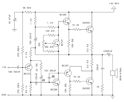
Simple and low cost. The optimal accumulation voltage is about 50V, but this amp assignment from 30 to 60V. The acute ascribe voltage is about 0.8 – 1V.
As you can see, in this architecture the apparatus accept a big tolerance, so you can body it about of the components, which you acquisition at home. The and transistors can be any NPN blazon ability transistor, but do not use Darlington types… The achievement ability is about 60W.
Amplifier
Click to view larger 2N3055 Power Amplifier Circuit Schematic Figure

- capacitor C1 regulates the low frequencies (bass), as the capacitance grows, the low frequncies are accepting louder.

- capacitor C2 regulates the college frequencies (treble), as the capacitance grows, the college frequencies are accepting quiter.

- this is a chic B amplifier, this means, that a accepted charge breeze through the end transistors, alike if there is no arresting on the input. This accepted can be adapted with the 500Ω trimmer resistor. As this accepted incrases, the complete of the amplifier gets better, but the end transistors are added heating. But if this accepted decrases, the transistors are not heating so much, but the complete gets worse…
Read More..

Booster BLW 60

In this post an opportunity, I upload booster BLW 60 which may be an inspiration to create home brew. Here I include a file layout that can be unlocked via software sprint layout. of course the software you can download here as well. ok g tuk need to talk at length, immediately wrote download the full data here


Read More..

Sunday, November 16, 2014

Stereo Amplifier with Tube

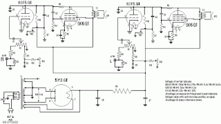
Stereo amplifier is very simple, consisting of 5 active components including the power supply it. Series Stereo Amplifier With Tube was prepared with 5 units trioda tube consisting of 1 unit tubes 5Y3 GT vacuum rectifier, 2 tube tube trioda 6SF5 GT high-mu tube 6k6 and 2 units which form the power beam amplifiers. Power consumption for the circuit with a tube stereo amplifier is not more than 45 Watt. Current consumption for the circuit with a tube stereo amplifier is around 3A. A complete range of stereo amplifiers with this tube can be seen from the following series of images.

Stereo Amplifier With Tube

Stereo


Sign Component Stereo Amplifier With Tube
R1, R10, R13 2.2M
R2 470K 1/2W
1 Meg 1/2W R3
R4 220K 1/2W
R5 330 Ohm 2W
R6 220K 1/2W
R7 2.2Meg 1/2W
R8 1Meg 1/2W
R9 720 Ohm 20W
R11 33K 1/2W
R12 22K 1/2W
C1, C9 400V 0.005uF
C2 0.05uF 600V
C3 20uF 25V
C4 0.01uF 400V
C5 200uuF 400V
C6, C7 15uF 450V
C8 15uF 400V
T1 117V Primary, Secondary 350VCT, 2 × 6.3V
T2 7600 Ohm Primary, Secondary 4 or 8 Ohm
SW1 SPST Switch
SP1, SP2 12 "4 / 8 ohm
C8 in the series stereo tube amplifier with the above serves to reduce radio frequency interference and to optimize the work of a wild series of ampifier stereo with these tubes.
Read More..

Saturday, November 15, 2014

SOUND OPERATED SWITCH

A sound operated switch with a relay driver. We have described a sound operated switch circuit which will switch ON the light by just listening sound. Another advantage of this circuit is that you cannot get any electrical shock as we did not have to use any mechanical switch.This sensitive sound operated switch can be used with a dynamic microphone insert as above, or be used with an electret (ECM) microphone. If an ECM is used then R1 (shown dotted) will need to be included. A suitable value would be between 2.2k and 10kohms.

Circuit Diagram


Notes

This sensitive sound operated switch can be used with a dynamic microphone insert as above, or be used with an electret (ECM) microphone. If an ECM is used then R1 (shown dotted) will need to be included. A suitable value would be between 2.2k and 10kohms.

The two BC109C transistors form an audio preamp, the gain of which is controlled by the 10k preset. The output is further amplified by a BC182B transistor. To prevent instability the preamp is decoupled with a 100u capacitor and 1k resistor. The audio voltage at the collector of the BC182B is rectified by the two 1N4148 diodes and 4.7u capacitor. This dc voltage will directly drive the BC212B transistor and operate the relay and LED. It should be noted that this circuit does not "latch". The relay and LED operate momentarily in response to audio peaks.

The gain of the circuit and sensitivity is controlled by the 10k variable resistor on the emitter of the first (left hand side) transistor. A preset may be used if gain is fixed, a potentiometer should be used to trigger at different sound levels.

The relay contacts close and then open (momentary action) in response to audio peaks, these can be used to switch other circuit. The diode across the relay is the usual back emf diode and a 1N4003 or 1N4004 will work well here, preventing damage to the transistor.
Read More..

Friday, November 14, 2014

WATER LEVEL CONTROLLER USING 8051

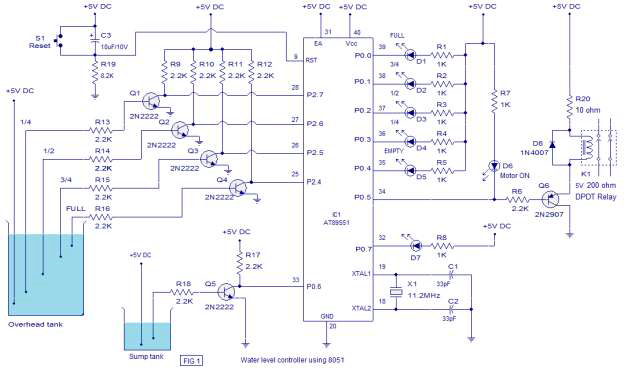
A water level controller based using 8051 is shown in this article. A lot of water level controller projects have been published in this website but the is the first one based on a microcontroller. This water level controller monitors the level of the overhead tank and automatically switches on the water pump whenever the level goes below a preset limit. The level of the overhead tank is indicated using 5 leds and the pump is switched of when the overhead tank is filled. The pump is not allowed to start if the water level in the sump tank is low and also the pump is switched off when the level inside the sump tank goes low during a pumping cycle. The circuit diagram of the water level controller is shown below.

The level sensor probes for the overhead tank are interfaced to the port 2 of the microcontroller through transistors. Have a look at the sensor probe arrangement for the overhead tank in Fig1. A positive voltage supply probe goes to the down bottom of the tank. The probes for sensing 1/4, 1/2, 3/4 and FULL levels are placed with equal spacing one by one above the bottom positive probe. Consider the topmost (full level) probe, its other end is connected to the base of transistor Q4 through resistor R16. Whenever water rises to the full level current flows into the base of transistor Q4 which makes it ON and so its collector voltage goes low. The collector of Q4 is connected to P2.4 and a low voltage at P2.4 means the overhead tank is not FULL. When water level goes below the full level probe, the base of Q2 becomes open making it OFF. Now its collector voltage goes high and high at P2.4 means the tank is not full. The same applies to other sensor probes (3/4, 1/2, 1/4) and the microprocessor understands the current level by scanning the port pins P2.4 ,P2.5, P2.6 and P2.7. All these port pin are high (all sensor probes are open) means the tank is empty.

Port pin P0.5 is used to control the pump. Whenever it is required start pumping, the controller makes P0.5 low which makes transistor Q6 ON which in turn activates the relay K1 that switches the pump. Also the LED d6 glows indicating the motor is ON. LED D7 is the low sump indicator. When the water level in the sump tank goes low, the controller makes P0.7 low which makes LED D7 to glow. The circuit diagram of the water level controller is shown in the figure below.

Circuit Diagram


Fig. 1

Program

MOV P2,#11111111B // initiates P2 as sensor input
MOV P0,#11111111B // initiates P2 as the output port
MOV A,#00000000B
MAIN : ACALL SMPCK // checks the level of the sump tank
       MOV A,P2 // moves the current status of P2 tp A
       CJNE A,#11110000B,LABEL1 // checks whether tank is full
       SETB P0.1
       SETB P0.2
       SETB P0.3
       SETB P0.4
       CLR P0.0 // glows full level LED
       SETB P0.5
LABEL1 : MOV A,P2
         CJNE A,#11111000B,LABEL2 // checks whether tank is 3/4
         SETB P0.0
         SETB P0.2
         SETB P0.3
         SETB P0.4
         CLR P0.1 // glows 3/4 level LED
LABEL2 : MOV A,P2
         CJNE A,#11111100B,LABEL3 // checks whether tank is 1/2
         SETB P0.0
         SETB P0.1
         SETB P0.3
         SETB P0.4
         CLR P0.2 // glows 1/2 level LED
LABEL3 : MOV A,P2
         CJNE A,#11111110B,LABEL4 // checks whether tank is 1/4
         SETB P0.0
         SETB P0.1
         SETB P0.2
         SETB P0.4
         CLR P0.3 // glows 1/4 level LED
         JB P0.6,LABEL4
         CLR P0.5 // switches motor ON
LABEL4 : MOV A,P2
         CJNE A,#11111111B,MAIN // checks whether tank is empty
         SETB P0.0
         SETB P0.1
         SETB P0.2
         SETB P0.3
         CLR P0.4 // glows EMPTY LED
         JB P0.6,MAIN // checks whether sump is low
         CLR P0.5 // switches motor ON
         SJMP MAIN
SMPCK : JB P0.6,LABEL5 // checks whether sump is low
        SETB P0.7 // extinguishes the sump low indicator LED
        SJMP LABEL6
LABEL5 : SETB P0.5 // switches the pump OFF
         CLR P0.7 // glows sump low indicator LED
LABEL6 : RET
Read More..

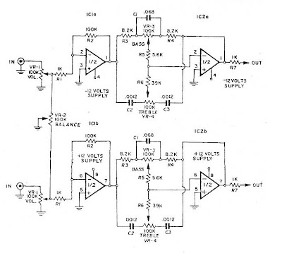
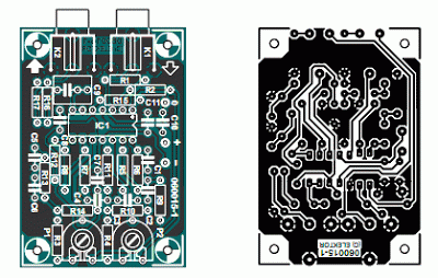
IC NE5532 x2 Tone Control Stereo bass treble


Read More..

Thursday, November 13, 2014

555 timer bassed Electronic lock circuit with explanation


A very simple electronic key code lock circuit that require few external components can be constructed using this schematic diagram . This electronic key code lock circuit is based on a common 555 timer circuit and some other common components .

This low cost key code circuit use six switches that needs to be pressed to open the lock, but only two switches at a time. In many other , more expensive electronic circuits the key code is formed by pressing some switches one by one , not like in this case two switches . If you don’t like to press two switches in the same time you can eliminate one switch , but in that case the code can be more easy to guess by someone ells .
Thus a total of three sets of switches have to be pressed in a particular sequence. (Of these three sets, one set is repeated.)

An essential property of this electronic code lock is that it works in monostable mode, i.e. once triggered, the output becomes high and remains so for a period of time, governed by the
timing components, before returning to the quiescent low state.

Pin 2 of 555 timer is the triggering input pin which, when held below 1/3 of the supply voltage, drives the output to high state. The threshold pin 6, when held higher than 2/3 of the supply voltage, drives the output to low state. By applying a low-going pulse to the reset pin 4, the output at pin 3 can be brought to the quiescent low level. Thus the reset pin 4 should be held high for normal operation of the IC.

Three sets of switches SA-SC, S1- S8 and S3-S4 are pressed, in that order, to open the lock. On pressing the switches SA and SC simultaneously, capacitor C3 charges through the potential
divider comprising resistors R3 and R4, and on releasing these two switches, capacitor C3 starts discharging through resistor R4. Capacitor C3 and resistor R4 are so selected that it takes about five seconds to fully discharge C3.

Depressing switches S1 and S8 in same time, within five seconds of releasing the switches SA and SC, pulls pin 2 to ground and IC 555 is triggered. The capacitor C1 starts charging through resistor R1. As a result, the output (pin 3) goes high for five seconds .
Within these five seconds, switches SA and SC are to be pressed momentarily once again, followed by the depression of last code-switch pair S3-S4.

These switches connect the relay to output pin 3 and the relay is energised.
The contacts of the relay close and the solenoid pulls in the latch (forming part of a lock) and the lock opens. The remaining switches are connected between reset pin 4 and ground. If any one of these switches is pressed, the IC is reset and the output goes to its quiescent low state.
The given circuit can be recoded easily by rearranging connections to the switches as desired by the user.
Read More..

Song Music generator circuit using ic UM66

This is a simple (song) music generator circuit using ic UM66. To make a musical calling-bell, door-bell, kids toys etc. we can use this funny audio/sound/music/tone generator ic UM66. The UM66 series are CMOS IC’s, they has a built in ROM to store the music. The IC operates in DC +3V. We suggest to use two dry cell (1.5V X 2) for +3V Supply.  For Q1 use a TO-92 type NPN transistor like BC548, BC168, BC183, BC238, 2N2222. Speaker must be 4Ω or higher.

Circuit Diagram of Music generator using ic UM66: 

um66
Fig: Circuit Diagram of Song-Music generator using IC-UM66


UM66TXX series IC generate different songs-music, the song-music depends on the model of UM66TXX series IC’s. The song-music are listed below with model number.

UM66TXX Songs List:
UM66T01 = Jingle Bells + Santa Claus is coming to town + Wish you a Merry Xmas
UM66T02 = Jingle Bells
UM66T04 = Jingle Bells + Rudolph, the red-nosed reindeer + Joy the world
UM66T05 = Home sweet home
UM66T06 = Let me call you sweetheart
UM66T08 = Happy birthday to you
UM66T09 = Wedding march
UM66T11 = Love me tender, Love me true
UM66T13 = Easter parade
UM66T19 = For Elise
UM66T32 = Waltz
UM66T33 = Mary had a little lamb
UM66T34 = The train is running fast
UM66T68 = Its small world
Read More..

Wednesday, November 12, 2014

LA4555 based Audio Amplifier circuit with explanation

LA4555

LA4555

Stereo circuit and mono circuit are given in schematic .LA 4555 is basically a stereo amplifier with 2.3 watts into 4 ohms speakers at a total distortion of 10%. With a bridge circuit, it can be configured as mono amplifier delivering 4.6 watts. It has an input impedance of 30K and gain of 51 dB. It has an excellent voltage range of 3 to 13 volts. Both mono and stereo circuits are shown here.

Pin out is given in Figure

LA4555

Input is given at Pin 8 in the mono circuit and output is taken at Pin 11 through a capacitor (C7) of 470 uF to a speaker of 4 ohms. In the case of stereo circuit, input is given at 5 and 8 pins and output is taken out at 2 and 11 pins respectively for left and right channels through the blocking capacitors C4 and C7.

A detailed description of the pin out will help now and in the future.

In the stereo circuit,

C5, C2 are feedback capacitors, zohich dictate the lower cut off frequency.

CI, C6 are bootstrap capacitors. If the capacitor value is reduced from the recommended 47uF, output

at flow frequencies falls.

Cll, CIO are oscillation blocking capacitors. Polyester film capacitors are preferable.

C7, C4 are output coupling capacitors. Lower cutoff frequency depends on their value and quality.

C3 is the ripple filter or decoupling capacitor.

C8, C9 are the power source capacitors.

R2, R2 are oscillation blocking resistors.

ICs dissipate heat as they dissipate more and more power at more and more voltages. The heat must be removed continuously such that IC operates at rated temperature. Failure to do so will result in thermal runaway. If the IC is well protected, output power will fall to a safe area. If not it will eventually fail and pack up. Copper foil area is made as large as possible in the vicinity ofIC to dissipate more heat.

Then heat sink, thermally conductive material such as copper or aluminum is mounted on IC to remove the heat as it develops. It must be of enough size. In case ofLA4555, the IC has fins which are soldered to the PCB and a small heat sink also can be soldered along with it. Solder copper heat sink as shown in the figure below. Aluminum cannot be easily soldered. Method of mounting heat sink is shown in Figure.

heat

readmore: www.engineeringslash.com/audio-circuits/la4555-audio-amplifier.html

Read More..

Simple LED flasher circuit using NE555 timer IC

This circuit consumes more power, but its advantage is when you need a variable flash rate, like for strobe circuits. You can actually use this circuit as a remote control for strobes that have a remote input. Of course, it has many other applications besides strobes.

  • R1, R2, C1 and the supply voltage determine the flash rate. Using a regulated power supply will do much to insure a stable flash rate. For a variable flash rate, replace R1 with a 1 megohm pot in series with a 22k resistor.
  • The duty cycle of the circuit (the percentage of the time LED 1 is on to the time it is off during each cycle) is deterimed by the ratio of R1 to R2. If the value of R1 is low in relationship to R2, the duty cycle will be near 50 percent. If you use both LEDs, you will probably want a 50 percent duty cycle. On the other hand, if R2 is low compared to R1, the duty cycle will be less than 50 percent. This is useful to conserve battery life, or to produce a strobe type effect, when only LED1 is used.
  • The NE555 timer chip can be damaged by reverse polarity voltage being applied to it. You can make the circuit goof proof by placing a diode in series with one of the supply leads.
  • The purpose of R3 and R4 is to limit current through the LEDs to the maximum they can handle (usually 20 milliamps). You should select the value of these according to the supply voltage. 470 ohms works well with a supply voltage of 9-12 volts. You will need to reduce the value for lower supply voltages.
  • Rainbow Kits offers several kits to build the above circuit. You can also order these kits from RadioShack.com. The Radio Shack catalog numbers (and web pages) are as follows: standard kit with two 5mm red LEDs, (990-0067), kit with two red, two green and two yellow 3mm LEDs, (990-0063), kit with jumbo green LEDs, (990-0048), kit with jumbo red LEDs, (990-0049). You can also buy all the parts to build the circuit at your local Radio Shack store, including a circuit board (276-159B).
Read More..

10 10 W Stereo Amplifier with tda2004

Hello! in this post I will show a small amplifier using integrated circuit TDA2004 get two outputs 10 watts, the circuit is very simple, if you want to change the circuit, or a mono version refer to the datasheet tda2004!
The circuit is powered by source between 12 and 15 volts with a current of 1.5 Amperes.
 
See the figure below:

Read More..

Tuesday, November 11, 2014

Stitching Machine Motor Speed Control circuit with explanation


Motor operated stitching machines have a series of carbon buttons in an enclosure operated by foot pedal. As the pressure on the foot pedal is increased or decreased by the foot, these buttons come close or move farther away, their resistance changes and hence the speed of the motor. Even though crude, it seemed to be okay, until my wife complained.

She said that the speed is little too fast even at the minimum pressure on the foot pedal, particularly for some repair work or at embroidery. Most of the housewives also like a little more control over speed of the machine. So here you have it.

The circuit is shown in Schematic 30. This is a standard triac speed control circuit much similar to domestic fan control circuit. Contrary to other triac circuits, you will find that an additional component known as diac is used in this circuit.

Triacsfire more symmetrically when used along with diac in AC power control applications. The diac is a bidirectional trigger diode which does not conduct (except for a small leakage current) until the break over voltage is reached. Its function is designed specifically to trigger a triac or SCR.

In the beginning triac Ql is not conducting; C1 is charged through variable resistor R3. This charge is coupled to Diac through R1, R3. When trigger level of the diac is reached (about 36 V), D1 fires and Triac TR1 is switched on. R3 and C1 combination sets the firing point of the triac from zero crossing along with Rl and R2. LI and C3 combination acts radio frequency filter for the radio interference caused by triac firing.

Entire circuit operates on mains. Care must be exercised when mounting components on normal Veroboard is risky. Remove alternate tracks and mount components. Triac should be mounted on a small heat sink as the triac tends to get hot particularly at lower speeds. All capacitors are polyester or polycarbonate rated at 600V or more. Rl is a preset for minimum speed control. Adjust this according to your requirement. R2 is the linear variable resistor like the volume control in the radios. Use the one with plastic shaft. L1 is a radio interference choke. Take 28 gage winding wire and make 10 turns on a 6 mm former. It can be wound on a round capacitor for C3 and even one end can be soldered to it also.

Read More..

Saturday, November 8, 2014

SMD transmitter circuit schematic

Let’s construct a low-power FM transmitter using surface-mount devices (SMD) that will be received with a standard FM radio. Soldering surface mounted devices is not so hard and actually is quite easy. There are many designs for small FM transmitters but they have some problems. First, you need an audio amplifier to get enough modulation. Second, the antenna is attached directly to the collector.

Third, the coil L must be wound by hand and adjusted by stretching. It all ads with a weak signal that tends to drift in frequency. In contrastm the transmitter schematic we present here eliminates some of those problems, using varactor diode for tuning and modulation, givind great sensitivity without an audio amplifier.


FM Transmitter – How it works

The figure below shows the schematic of the transmitter which consists of two stages: an oscillator and an output amplifier. Modulation is from an electret microphone but you can use a low power audio source.

Oscillator stage

Transistor Q1 is a Colpitts oscillator where the frequency is determined by the parallel resonant circuit formed by inductor L, varactor V1 and capacitors C7 and C8. Q1 is a common-collector amplifier where the power gain counts. V1 is actually a dual varactor that eliminate the possibility of forward conduction at the sinewave peaks.

The frequency of oscillation is set by adjusting the DC voltage on V1 with potentiometer R2. R4 and C3 form a low-pass filter to prevent RF from feeding back onto the DC.
Capacitors C7 and C8 form an AC voltage divider to provide feedback at the emitter of Q1 to sustain oscillation. A necessary condition for oscillation to start is for the radio (C7+C8)/C7 to be sufficiently bigger than 1.

SMD transmitter circuit schematic
 

Frequency Modulation

Modulation is done by superimposing an audio signal from the electret mic onto the DC bias applied to V1. R3 and C1 form a low-pass filter to prevent RF from feeding back to the mic. R3, R4 and R2 form a votage divider for the audio.

Transmitter output stage

The output of the oscillator is fed through C9 to the Q2 emitter-follower. The output of Q2 drives the antenna through C11. The Q2 emitter-follower it ensures that the oscillator is not loaded down by the impedance of the antenna and it provides power gain to drive the antenna.

SMD Transmitter layout

The figure below shows the layout of the PCB and it uses surface-mounted devices like resistors and capacitors (non-polar devices). All the caps are size 0805 and all resistors are size 1206. use through-hole components for Q1, Q2, IC1 and V1. You can use an SOT-89 device for IC1 and an SOT-23 device for V1. Use MPSH10 or a transistor equivalent. Here you can learn how to solder smd chips


 The inductor

A coil would consist of two or three turns of wire but for this schematic we will use an inductor with loops of copper on the PCB. Such flat spiral inductor are common at these frequencies.
One formula for flat spiral inductors is:
flat spiral inductors formula where
L = inductance in uH
r = radius of coil (outer radius + inner radius divided by 2 ) inches
N = number of turns
d = depth of coil (outer radius minus inner radius) inches

Tuning range

While commercial FM band goes from about 88 MHz to 108 MHz, the L and C values used in this design allow tuning up to 100 MHz.

Transmitter testing

You will need a portable FM radio and an assistant. First, find an empty spot on the FM dial and set your radio about 30 feet away (9 meters). The radio’s volume control should not be set too high to prevend feedback. Next, power-up your transmitter and talk to yourself as you adjust the frequency with the trim-pot. When your assintant hears you, your transmitter is tuned. You might have to adjust the radio’s tuner slightly for best reception.

Have fun with it but remember that using the transmitter as a bugging device may not be legal in your country. To use the circuit as a wireless microphone, increase the value of R3. The transmitter range is about 100 feet (30 meters) inside a building.

Parts list

Read More..

Studio Series Stereo Headphone Amplifier

Heres a top-class headphone amplifier that can drive high or low impedance phones to full power levels, with very low noise and distortion. For best performance, it can be teamed with the Stereo Preamplifier described last month. Alternatively, it can be used as a standalone unit, requiring only a power supply and a volume control pot for use with any line-level signal source (CD/MP3 player etc). It even includes dual outputs, so you can listen with a friend!

Picture of the circuit:


Many of our high-power audio amplifier designs already provide an output for headphones. The additional circuitry required for headphone support is simple; just two resistors in series with the loudspeaker outputs to limit the drive current and protect the ’phones in the case of amplifier failure.

Considering its simplicity, this resistive limiting scheme works well, although it will cause distortion if the load is non-linear – a likely prospect with most headphones. Apart from eliminating this potential source of distortion, there are a number of other reasons why you might consider building a separate headphone amplifier.

For a start, not everyone owns a pair of top-rated headphones or even a high-performance power amplifier. After all, an amplifier that equals or betters the performance of this new headphone amplifier will set you back more than a few shekels!

Parts layout:


Another reason might be for use with the latest "high-tech" audio electronics gear. The headphone outputs in much of this gear cannot drive low-impedance ’phones – or at least not to decent listening levels. In addition, available output power in portable devices is deliberately limited to conserve battery energy. This means that lots of distortion might be present at higher listening levels, even with sensitive headphones.

One way around this is to feed the line-level outputs of this gear into your power amplifier and then plug your low-impedance headphones into that. That works but then you’re tethered to an immovable object. Besides, the power required to drive headphones is around 1/1000th of that required to drive loudspeakers, so a large power amplifier could be considered a tad oversized for the job!

Circuit diagram:


Main Features:

    High performance – very low noise & distortion
    Drives high and low-impedance headphones
    High output power (up to 200mW; into 8? and 32?)
    Dual headphone sockets – can drive two pairs!
    Works with a preamp or any line-level audio source

Measured Performance:

Frequency response.......................... flat from 10Hz to 20kHz (see graphs)
Rated output power........................... 200mW into 8? and 32?, 85mW into 600?
Max. output power (current or voltage limited)...............575mW into 8?, 700mW into 32?, 130mW into 600?
Harmonic distortion........................ typically .0005% (600? load),.001% (32? load) and .005% (8? load)
Signal-to-noise ratio (A-weighted)......................... -130dB (600?), -120dB (32?) and -111dB (8?) with respect to 100mW output power.
Channel crosstalk.................. better than -68dB from 20Hz-20kHz at 100m? output power (see graphs)
Input impedance.................................... ~47k? || 47pF
Output impedance..................... ~5?

Note:

All tests were performed with the amplifier driven from low source impedance. For crosstalk measurements, the non-driven input was back-terminated into 600?. 
Read More..

Condenser Mic Audio Amplifier

The compact, low-cost condenser mic audio amplifier described here provides good-quality audio of 0.5 watts at 4.5 volts. It can be used as part of intercoms, walkie-talkies, low-power transmitters, and packet radio receivers. Transistors T1 and T2 form the mic preamplifier. Resistor R1 provides the necessary bias for the condenser mic while preset VR1 functions as gain control for varying its gain. In order to increase the audio power, the low-level audio output from the preamplifier stage is coupled via coupling capacitor C7 to the audio power amplifier built around BEL1895 IC.

Circuit diagram:


BEL1895 is a monolithic audio power amplifier IC designed specifically for sensitive AM radio applications that delivers 1 watt into 4 ohms at 6V power supply voltage. It exhibits low distortion and noise and operates over 3V-9V supply voltage, which makes it ideal for battery operation. A turn-on pop reduction circuit prevents thud when the power supply is switched on. Coupling capacitor C7 determines low-frequency response of the amplifier. Capacitor C9 acts as the ripple-rejection filter.

Capacitor C13 couples the output available at pin 1 to the loudspeaker. R15-C13 combination acts as the damping circuit for output oscillations. Capacitor C12 provides the boot strapping function. This circuit is suitable for low-power HAM radio transmitters to supply the necessary audio power for modulation. With simple modifications it can also be used in intercom circuits.

Author: D. Prabakaran - Copyright: Electronics For You Mag
Read More..

Friday, November 7, 2014

Room Noise Detector Schematic Circuit

This circuit is intended to signal, through a flashing LED, the exceeding of a fixed threshold in room noise, chosen from three fixed levels, namely 50, 70 & 85 dB. Two Op-amps provide the necessary circuit gain for sounds picked-up by a miniature electret microphone to drive a LED. With SW1 in the first position the circuit is off. Second, third and fourth positions power the circuit and set the input sensitivity threshold to 85, 70 & 50 dB respectively. Current drawing is 1mA with LED off and 12-15mA when the LED is steady on.

Circuit diagram :
Room Noise Detector Circuit diagram

Parts List :R1____________10K 1/4W Resistor
R2,R3_________22K 1/4W Resistors
R4___________100K 1/4W Resistor
R5,R9,R10_____56K 1/4W Resistors
R6_____________5K6 1/4W Resistor
R7___________560R 1/4W Resistor
R8_____________2K2 1/4W Resistor
R11____________1K 1/4W Resistor
R12___________33K 1/4W Resistor
R13__________330R 1/4W Resistor

C1___________100nF 63V Polyester Capacitor
C2____________10µF 25V Electrolytic Capacitor
C3___________470µF 25V Electrolytic Capacitor
C4____________47µF 25V Electrolytic Capacitor

D1_____________5mm. Red LED

IC1__________LM358 Low Power Dual Op-amp

Q1___________BC327 45V 800mA PNP Transistor

MIC1_________Miniature electret microphone

SW1__________2 poles 4 ways rotary switch

B1___________9V PP3 Battery

Clip for PP3 BatteryUse :
  • Place the small box containing the circuit in the room where you intend to measure ambient noise.
  • The 50 dB setting is provided to monitor the noise in the bedroom at night. If the LED is steady on, or flashes bright often, then your bedroom is inadequate and too noisy for sleep.
  • The 70 dB setting is for living-rooms. If this level is often exceeded during the day, your apartment is rather uncomfortable.
  • If noise level is constantly over 85 dB, 8 hours a day, then you are living in a dangerous environment.
Read More..

Thursday, November 6, 2014

Very Low Power 32kHz Oscillator

The 32-kHz low-power clock oscillator offers numerous advantages over conventional oscillator circuits based on a CMOS inverter. Such inverter circuits present problems, for example, supply currents fluctuate widely over a 3V to 6V supply range, while current consumption below 250 µA is difficult to attain. Also, operation can be unreliable with wide variations in the supply voltage and the inverter’s input characteristics are subject to wide tolerances and differences among manufacturers. The circuit shown here solves the above problems. Drawing just 13 µA from a 3V supply, it consists of a one-transistor amplifier/oscillator (T1) and a low-power comparator/reference device (IC1).


Very Low Power 32kHz Oscillator Circuit Diagram

The base of T1 is biased at 1.25 V using R5/R4 and the reference in IC1. T1 may be any small-signal transistor with a decent beta of 100 or so at 5 µA (defined here by R3, fixing the collector voltage at about 1 V below Vcc). The amplifier’s nominal gain is approximately 2 V/V. The quartz crystal combined with load capacitors C1 and C3 forms a feedback path around T1, whose 180 degrees of phase shift causes the oscillation. The bias voltage of 1.25 V for the comparator inside the MAX931 is defined by the reference via R2. The comparator’s input swing is thus accurately centred around the reference voltage.

Operating at 3 V and 32 kHz, IC1 draws just 7 µA. The comparator output can source and sink 40 mA and 5 mA respectively, which is ample for most low-power loads. However, the moderate rise/fall times of 500 ns and 100 ns respectively can cause standard, high-speed CMOS logic to draw higher than usual switching currents. The optional 74HC14 Schmitt trigger shown at the circuit output can handle the comparator’s rise/fall times with only a small penalty in supply current.
Read More..

Paraphase Tone Controller

As opposed to the widespread Baxandall circuit (dating back to 1952!) a ‘paraphrase’ tone control supplies a straight frequency response as long as the bass and treble controls are in the same position. This unique property makes the ‘paraphase’ configuration of interest if only treble or bass needs to be adjusted - it is not possible to adjust both at the same time! Essentially, it’s the difference in setting of the tone controls that determines the slope of the frequency response, and the degree of bass/treble correction. The circuit is simplicity itself, based on two networks C1-C2-C3/R9-R10-R11 and C5-C6-C7/R12-R13-R14.

Paraphase Tone Controller Circuit Picture:

Tone

The first is for the high frequencies (treble) response, the second, for the low frequencies (bass). The roll-off points have been selected, in combination with C4 and C8, for the sum of the two output signals to re-appear with a ‘straight’ frequency response again at the output. Roughly equal output levels from the networks are ensured by R6 = 7.15 k and R8 = 6.80 k. However, the operating principle requires the input signals to the two networks to be in anti-phase. For best operation the networks are driven by two buffers providing some extra gain.

Paraphase Tone Controller Circuit diagram:
Tone

The gain of IC1.D is slightly higher than that of IC1.C to ensure the overall response curve remains as flat as possible at equal settings of the tone controls. Because each network introduces a loss of about 1.72 (times), IC1.D and IC1.C first amplify the signal. The gain is set at about 8 (times) allowing input signal levels up to 1 V to pass the circuit at maximum gain and distortion-free. The gain also compensates the attenuation if you prefer to keep the tone controls at the mid positions for a straight response.

Parts and PCB layout:
 parts and pcb layout


To audio fans, the circuit is rewarding to experiment with, especially in respect of the crossover point of the two networks. R3 and R4 determine the control range, which may be increased (within limits) by using lower resistor values here. The values shown ensure a tone control range of about 20 dB. IC1.B buffers the summed signal across R15. C9 removes any DC-offset voltage and R16 protects the output buffer from the effects of too high capacitive loads. R17, finally, keeps the output at 0 V. The choice of the quad opamp is relatively uncritical. Here the unassuming TL074 is used but you may even apply rail to rail opamps as long as they are stable at unity gain. Also, watch the supply voltage range. A simple circuit board was designed for the project. Linear-law potentiometers may be fitted directly onto the board. Two boards are required for a stereo application. The relevant connections on the boards are then wired to a stereo control potentiometer.

Specification:
  • Current consumption (no signal) 8 mA
  • Max. input signal 1 Veff (at max. gain)
  • Gain at 20 Hz +13.1 dB max. –6.9 dB min.
  • at 20 kHz +12.2 dB max. –7.6 dB min
  • Gain (controls at mid position) 2.38 x
  • Distortion (1 Veff, 1 kHz) 0.002% (B = 22kHz) 0.005% (B = 80 kHz)
COMPONENTS LIST
Resistors
R1-R4 = 10k
R5,R7 = 1k
R6 = 7k15
R8 = 6k80
R9,R10,R11 = 8k2
R12,R13,R14 = 2k2
R15 = 1M
R16 = 100R
R17 = 100k
P1,P2 = 100k preset or chassis-
mount control potentiometer, linear law
Capacitors
C1,C2,C3 = 47nF MKT, lead pitch 5mm
C4 = 68nF MKT, lead pitch 5mm
C5,C6,C7 = 10nF MKT, lead pitch 5mm
C8,C10,C11 = 100nF MKT, lead pitch 5mm
C9 = 2µF2 MKT, lead pitch 5mm or 7.5mm
Semiconductors
IC1 = TL074
Miscellaneous
K1,K2 = line socket, PCB mount, e.g.
T-709G (Monacor/Monarch)


Read More..

Laser Controlled ON OFF Switch

This circuit is built around a 555 timer using very few components. Since the circuit is very simple, even a novice can easily build it and use it as a controlling device. A laser pointer, now easily available in the market, can be used to operate this device. This circuit has been tested in operational conditions from a distance of 500 meters and was found to work satisfactorily,though it can be controlled from still longer distances.
Circuit diagram :
Laser Controlled ON/OFF Switch Circuit Diagram

Aiming (aligning) the laser beam exactly on to the LDR is a practical problem. The circuit is very useful in switching on/off a fan at night without getting off the bed. It can also be used for controlling a variety of other devices like radio or music system. The limitation is that the circuit is operational only in dark or dull lit environments.

By focusing the laser beam on LDR1 the connected gadget can be activated through the relay, whereas by focusing laser beam on LDR2 we can switch off the gadget. The timer is configured to operate in bitable mode. The laser pointers are available for less than Rs 150 in the market. The cost of the actual circuit is less than Rs 50.
Read More..

Wednesday, November 5, 2014

Simple Electronic Code Lock

The circuit diagram of a simple electronic code lock is shown in figure. A 9-digit code number is used to operate the code lock.When power supply to the circuit is turned on, a positive pulse is applied to the RESET pin (pin 15) through capacitor C1. Thus, the first output terminal Q1 (pin 3) of the decade counter IC (CD 4017) will be high and all other outputs (Q2 to Q10) will be low. To shift the high state from Q1 to Q2, a positive pulse must be applied at the clock input terminal (pin 14) of IC1. This is possible only by pressing the push-to-on switch S1 momentarily.

Simple Electronic Code Lock Circuit diagram:
 
Electronic


On pressing switch S1, the high state shifts from Q1 to Q2. Now, to change the high state from Q2 to Q3, apply another positive pulse at pin 14, which is possible only by pressing switch S2. Similarly, the high state can be shifted up to the tenth output (Q10) by pressing the switches S1 through S9 sequentially in that order. When Q10 (pin 11) is high, transistor T1 conducts and energises relay RL1. The relay can be used to switch ‘on’ power to any electrical appliance. Diodes D1 through D9 are provided to prevent damage/malfunctioning of the IC when two switches corresponding to ‘high’ and ‘low’ output terminals are pressed simultaneously.

Capacitor C2 and resistor R3 are provided to prevent noise during switching action. witch S10 is used to reset the circuit manually. Switches S1 to S10 can be mounted on a keyboard panel, and any number or letter can be used to mark them. Switch S10 is also placed together with other switches so that any stranger trying to operate the lock frequently presses the switch S10, thereby resetting the circuit many times. Thus, he is never able to turn the relay ‘on’. If necessary, two or three switches can be connected in parallel with S10 and placed on the key-board panel for more safety. A 12V power supply is used for the circuit. The circuit is very simple and can be easily assembled on a general-purpose PCB. The code number can be easily changed by changing the connections to switches (S1 to S9).
Read More..

Simple Clever Rain Alarm

Usually rain-alarms employ a single sensor. A serious draw-back of this type of sensor is that even if a single drop of water falls on the sensor, the alarm would sound. There is a probability that the alarm may be false. To overcome this draw-back, here we make use of four sensors, each placed well away from the other at suitable spots on the roof. The rain alarm would sound only if all the four sensors get wet. This reduces the probability of false alarm to a very great extent. The four rain-sensors SR1 to SR4, along with pull-up resistors R1 to R4 (connected to positive rails) and inverters N1 to N4, form the rain-sensor monitor stage. The sensor wires are brought to the PCB input points E1 to E5 using a 5-core cable. The four outputs of Schmitt inverter gates N1 to N4 go to the four inputs of Schmitt NAND gate N7, that makes the alarm driver stage.

Clever Rain-Alarm Circuit Diagram

Alarm

When all four sensors sense the rain, all four inputs to gates N1 through N4 go low and their outputs go high. Thus all four in-puts to NAND gate N7 also go high and its output at pin 6 goes to logic 0. The out-put of gate N7 is high if any one or more of the rain-sensor plates SR1 through SR4 remain dry. The output of gate N7 is coupled to inverter gates N5 and N6. The output from gate N5 (logic 1 when rain is sensed) is brought to  ‘EXT’ output connector, which may be used to control other external devices.

The output from the other inverter gate N6 is used as enable input for NAND gate N8, which is configured as a low-frequency oscillator to drive/modulate the piezo buzzer via transistor T1. The frequency of the oscillator/modulator stage is variable between 10 Hz and 200 Hz with the help of preset VR1. The buzzer is of piezo-electric type having a continuous tone that is inter-rupted by the low-frequency output of N8. The buzzer will sound whenever rain is sensed (by all four sensors). 6V power supply (100mA) is used here to enable proper interfacing of the CMOS and TTL ICs used in the circuit. The power supply requirement is quite low and a 6-volt battery pack can be easily used. During quiscent-state, only a negligible cur-rent is consumed by the circuit.
Clever
Even during active state, not more than 20mA current is needed for driving a good-quality piezo-buzzer. Please note that IC2, being of TTL type, needs a 5V regulated supply. There-fore zener D1, along with capacitor C2 and resistor R5, are used for this purpose.A parallel-track, general-purpose PCB or a veroboard is enough to hold all the components. The rain-sensors SR1 to SR4 can be fabricated as shown in the construction guide in Fig. 2. They can be made simply by connecting alternate parallel tracks using jumpers on the component side.

Use some epoxy cement on and around the wire joints at A and B to avoid corrosion. Also, the sensors can be cemented in place with epoxy cement. If the number of sensors is to be increased, just add another set of CD40106 and 7413 ICs along with the associated discrete components. Another good utility of the rain-alarm is in agriculture. When drip-irrigation is employed, fix the four sensors at four corners of the tree-pits, at a suit-able height from the ground. Then, as soon as the water rises to the sensor’s level, the circuit can be used to switch off the water pump.


Read More..

A Low Distortion Audio Pre amplifier

In an audio amplifier the quality of sound depends upon a number of factors, e.g. quality of active and passive components, circuit configuration, and layout. To an extent, the selection of components depends on the constructor’s budget. The discrete active components like transistors have been increasingly replaced by linear ICs, making the task of designer easier. With the passage of time, the general-purpose op-amps like LM741, which were being used in audio/hi-fi circuits, have become The preamplifier circuit presented here is based on a dual precision op-amp for the construction of a low distortion, high quality audio preamplifier.

Low Distortion Audio Pre-amplifier Circuit Diagram:

A dual op-amp OPA2604 from Burr-Brown is used for all the stages. The FET input stage op-amp was chosen in this context it is worthwile to mention another popular bi-polar architecture op-amp, the NE5534A. It has, no doubt, an exceptionally low noise figure of 4nV/ÖHz but rest of the specifications compared to OPA2604 are virtually absent in this IC. Also This IC is also capable of operating at higher voltage rails of ± 24V (max.). Also its input bias current (100 pA) is many orders lower than its bipolar counterpart’s. This ensures a multifold reduction in noise.

A channel seperation of 142 dB exists between In the circuit, buffer is essential for the proper working of the subsequent blocks. A nominal input impedance of 47k is offered by this stage which prevents overloading of the preamplifier. The tone control is a baxandall type filter circuit.The bandwidth limiter is basically a low-pass filter with an upper cut-off ceiling at the end of the useful audio spectrum. The gain at 10 kHz is approximately 17 dB.

The design is essentially 3-pole type and the upper frequency is set at 25 kHz. This lSetting the unit is fairly simple. Check the power leads feeding the IC for symmetrical voltages. High quality audio output from the line output socket is to be fed as the input signal to this preamplifier. Output of the preamplifier is fed to the power a The whole circuit consumes about 10 mA when the above-mentioned ICs are used. Power supply requirements are not critical as the circuit works on 7.5V to 15V DC.
Read More..

Tuesday, November 4, 2014

Stereo Amplifier with Voltage Regulators

A simple stereo audio amplifier is built around two 7905 negative-voltage regulators (IC1 and IC2) and a few discrete components. The circuit will also work with other 79XX regulators if appropriate power supply is used. Regulator IC 7905 works as an amplifier for the voltages applied to common pin2 (Ground or GND). Also check the LM317 audio amplifier, another interesting circuit.
The minimal voltage drop over the standard 7905 is around 2V and it depends on the output current. Feedback resistors in the IC set the gain of the channel internally. The amplifier is a class-A audio amplifier. The minimal applicable value of R3 for the regulator 7905 is 8.2 to 10 ohms per 5W.

1W Stereo Amplifier with Voltage Regulators Circuit Diagram:

A

If the required output current for LS1 is below 100 mA, the value of resistor R3 can be 33 to 51 ohms per watt. The circuit works with any load resistance (R3 in parallel with LS1 as the load) under the condition that the regulator is not overloaded with current and power dissipation. However, it is preferable to use a loudspeaker with a high resistance (8 ohms, 16 ohms or more). The amplifier works well with low-impedance headphones having a resistance of 24 to 32 ohms. The voltage difference between the ground pin of 7905 and the output pin is fixed internally.
S2 is the on/off switch. Switch S1 is for mono/stereo selection. When switch S1 is closed, the amplifier works as a two-way mono amplifier. If S1 is open, the amplifier works as a stereo amplifier. If no input signal is applied, the DC voltage on the output of the regulator 7905 should be around –5V, which depends to some extent on the value of VR1. The maximum output current of 7905 can be up to 1A and the maximum power dissipation is up to 15W. Mount the regulator IC 7905 on a heat-sink with thermal resistance below 15°C/W.


Read More..